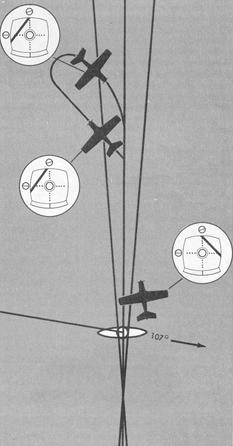
Where radar vectors are available on approach control frequencies, you will normally be vectored to the final approach course without executing a procedure turn. Assume in this instance that you are doing your own navigating. Over VOR "A", note the time of reversal from a "TO" to a "FROM" indication, and turn to transition from the outer fix to the outer compass locator (LOM) on the 107 radial. Transition bearing and distances are shown on approach charts enabling you to estimate time from outer fixes to final approach fixes. Position over the LOM can be established with either an ADF receiver or marker beacon receiver. When the ADF needle or marker beacon receiver indicates passage over the final approach fix, turn left to intercept and track outbound on the localizer front course. See Figure 8-13.
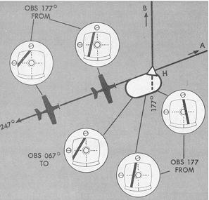
Figure 8-12. Holding: VOR receiver indications.
|
Figure 8-13. Transition to localizer course.
 |
Because of the narrow localizer course width, overcontrolling of heading corrections is a common error during localizer course tracking. Unless the CDI shows a full deflection, heading corrections in 5° increments (or less) should keep you close to the centerline. The sooner you establish the correct drift-correction angle, the easier it will be to track without chasing the localizer needle.
Time from the LOM to procedure turn entry depends upon the type of procedure turn to be executed, type of aircraft, wind velocity, and distance restrictions shown on the approach chart. CDI deflections during a standard procedure turn on the front course are illustrated in Figure 8-13. When turning inbound in to the localizer course, cross-check of the CDI should be frequent to prevent overshooting the course centerline. If your interception angle is 45° as shown, start the turn to the inbound course as soon as the CDI moves from the full deflection position.
Once you have reached the localizer centerline, maintain the inbound heading until the CDI moves off center. Drift corrections should be small and reduced proportionately as the course narrows. By the time you reach the outer marker, your drift correction should be established accurately enough on a well executed approach to permit completion of the approach with heading corrections no greater than 2°.
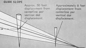
The heaviest demand on pilot technique occurs during descent from the outer marker to the middle marker, when you maintain the localizer course, adjust pitch attitude to maintain the proper rate of descent, and adjust power to maintain proper airspeed. Simultaneously, the altimeter must be checked and preparation made for visual transition to land or for a missed approach. The need for accurate instrument interpretation and aircraft control can be appreciated, in the complete ILS, by noting the relationship between CDI/glide path needle indications and aircraft displacement from the localizer and glide path centerlines. See Figures 8-14 and 8-15.
Figure 8-14. Localizer receiver indications and aircraft displacement.
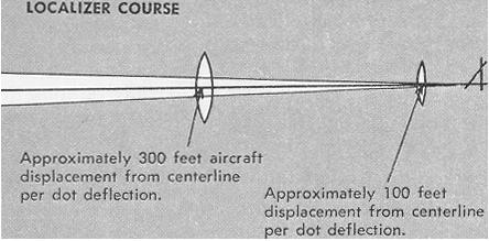 |
Figure 8-15. Glide slope receiver indications and aircraft displacement.
 |