Knowledge of ADF procedures offers several advantages to the instrument pilot, although many seldom use ADF equipment because of the relatively simpler operation and interpretation of VHF equipment. ADF provides: (a) a backup navigation system in the event of VHF equipment failure; (b) a means of monitoring position enroute and providing data for plotting fixes; (c) a navigation system for use in areas and at altitudes where VOR "line-of-sight" signals are unreliable; (d) radio communications (receiver only) on the ground where VHF reception is impossible. Weather broadcasts and clearances can be received, for example, at points outside VHF signal range; and (e) auxiliary and standby navigation information on instrument approaches.
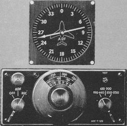
Selection of Station. An older type ADF receiver is shown in Figure 8-21, and has been described earlier on pages 124 and 125. The receiver illustrated can be tuned to any station between 190-1750 kHz. Included in this range are "H" facilities on Enroute Low Altitude Charts.
Figure 8-21. ADF receiver
|
Tuning. Tuning details vary with the type ADF equipment installed in the aircraft. The manufacturer's brochure provided with the particular receiver will include the necessary operating information. The modern crystal-controlled digitally-tuned ADF previously discussed on page 125 eliminates manual tuning. The older type ADF (Fig. 8-21) is tuned to a stations as follows:
1. Adjust the frequency band selector to the desired band.
2. Rotate the volume knob clockwise to approximately half the
range.
3. Select "REC" position on the function switch. This selects
the sense antenna for tuning the station for use of the receiver as a nondirectional
radio receiver. Tuning with the function switch on "ADF" (automatic) position
results in unnecessary hunting of the ADF needle as various station signals
are received.
4. Rotate the frequency selector to the desired frequency. If
a tuning meter is installed with the receiver, it is essential to tune
for maximum tuning meter deflection. Without a tuning meter, adjust the
frequency selector for maximum signal clarity and identify the station.
5. Select the "ADF" position on the function switch. The ADF
needle will rotate until it points to the station. Note the bearing indicated
on the ADF dial and push the "test" button. This will rotate the needle
clockwise until the test button is released. If the station is tuned properly
and the signal is reliable, the needle will return to the bearing previously
noted.
6. Adjust the volume to the desired level. Volume adjustment
has no effect on operation of the ADF needle.
ADF Orientation. Unlike the VOR receiver, which indicates magnetic
bearing TO or FROM the station without reference to aircraft heading, the
ADF needle points TO the station, regardless of aircraft heading or position.
The relative bearing indicated is thus the angular relationship between
the aircraft heading and the station, measured clockwise from the nose
of the aircraft.
A bearing is simply the direction of a straight line between
the aircraft and station, or vice-versa. The bearing line measured clockwise
from the nose of the aircraft is a relative bearing; measured clockwise
from true north, it is a true bearing; measured clockwise from magnetic
north, it is a magnetic bearing (Fig. 8-22 and Fig. 8-23). As the illustrations
show, a true, magnetic, or compass heading is measured clockwise from the
appropriate north, and a relative bearing is measured clockwise from the
nose of the aircraft. Thus, the true, magnetic, or compass bearing to the
station is the sum of true, magnetic, or compass heading, respectively,
and the relative bearing.
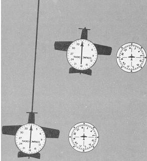
You will probably orient yourself more readily if you think in terms of nose/tail and left/right needle indications, visualizing the ADF dial in terms of the longitudinal axis of the aircraft. When the needle points to 0°, the nose of the aircraft points directly to the station; with the pointer on 210°, the station is 30° to the left of the tail; with the pointer on 090°, the station if off the right wing tip (Fig. 8-24). Thus, to turn directly toward station A, turn left 150° since the needle points to the left of the nose/tail line 30° from the tail position. Station B is 90° to the right; therefore turn right 90° to head directly toward the station.
Figure 8-22. ADF bearings.
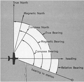 |
True bearing to station = TH + rel. bearing.
Magnetic bearing to station = MH + rel. bearing.
Station to aircraft bearings are true, magnetic or compass bearings
± 180°.
Figure 8-23. ADF bearing computations.
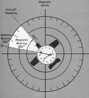 |
Magnetic bearing to station = magnetic heading (320°) + rel. bearing (320°) = 640° or 280° (whenever the total is greater than 360°, subtract 360 from the bearing).
Figure 8-24. ADF relative bearings.
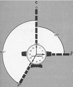 |
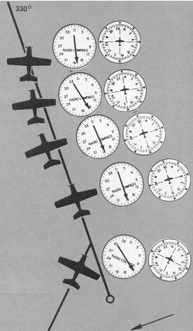
Figure 8-25. Determining magnetic bearing to station with ADF.
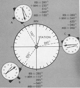 |
Note that (a) the relative bearing shown on the ADF dial does not, by itself, indicate aircraft position, and (b) the relative bearing must be related to aircraft heading to determine direction to or from the station (Fig. 8-25).
Figure 8-25 shows only one of several methods of determining bearings - or lines of position - between aircraft and station. Visualizing the 80° left-of-nose indication at all three positions shown, the magnetic bearing to station can be determined by subtracting the left deflection from the magnetic heading:
A B C
Magnetic heading......... 230° 115°
340°
Minus left deflection.... 80° 80°
80°
---- ---- ----
Magnetic bearing......... 150° 035°
260°
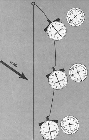
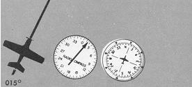
Homing. ADF homing is flying the aircraft on any heading required to keep the azimuth needle on 0° until the selected station has been reached (Fig. 8-26). To head the aircraft toward the station, turn to the heading that will zero the ADF needle. The heading indicator, rather than the ADF, should be used to make the turn. At the completion of the initial turn toward the station, check with the ADF needle and, if necessary, zero it with small corrections.
For example, Figure 8-26 shows an initial magnetic heading of 050° and a relative bearing of 302°. A left turn of approximately 60° should zero the needle, heading 350°. After the needle is zeroed, it will remain so unless the heading is changed or crosswind affects the aircraft track. If there is no wind, the aircraft will follow a straight track to the station, assuming constant heading. If a crosswind drifts the aircraft, the homing track will be a curve as you keep the ADF needle zeroed.
Figure 8-26. ADF homing.
 |
|
 |
Approach to the station is indicated by increasingly frequent heading corrections to zero the needle, especially when a strong crosswind exists, and by side-to-side needle deflections very close to the station. Passage directly over the station is shown by a 180° reversal of the ADF needle to the tail position; passage on either side and close to the station is shown by a rapid swing of the needle as it continues to point to the station. Homing is easy, though seldom used during instrument flying. Competent pilots control track by more precise procedures.
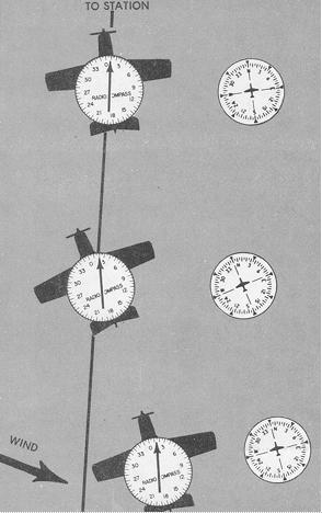
Tracking. A straight geographic flight path can be followed to or from a low (or medium) frequency facility by establishing a heading that will maintain the desired track regardless of wind effect. ADF tracking procedures involve interpretation of the heading indicator and azimuth needle to intercept and hold a desired magnetic bearing.
Inbound Tracking (Fig. 8-27). To track inbound, turn to the heading that will zero the ADF needle. As you hold this heading, deflection of the ADF needle to left or right shows a crosswind (needle left/wind from left; needle right/wind from right). When a definite change in azimuth (2° - 5°) shows that the aircraft has drifted off course, turn in the direction of needle deflection (into the wind) to reintercept the initial inbound bearing. The angle of interception must always be greater than the number of degrees of drift. The magnitude of any intercepting turn depends upon the observed RATE of bearing change, true airspeed, and how quickly you want to return to course.
A rapid rate of bearing change, while heading is constant, indicates either a strong crosswind or proximity to the station, or both. For example, if you are 60 miles from the station with a degree left deflection, your aircraft is 3 miles to the right of the desired course. In a slow aircraft, use a large interception angle for quick return to the course. In a very fast aircraft, the same interception angle could result in overshooting the desired course. Likewise, the same 3° needle deflection closer to the station means less deviation from the desired course, and smaller angles of interception result in rapid return to course. Again, when aircraft is 60 miles from the station, a rapid rate of bearing change indicates a strong crosswind; at half that distance, the same rate of bearing change means twice the crosswind effect, or conversely, at half the distance, the same wind effect results in double the rate of bearing change.
At a given angle of interception and with a given wind, rate of closure with the desired track varies directly with true airspeed. At 150 knots TAS as compared with 100 knots TAS, the effectiveness of a given interception angle is proportionately greater for the same wind at the same distance from the station. Having determined the angle of interception for return to the desired track, turn toward the track, by that amount. As you make the turn with the heading indicator, the azimuth needle rotates opposite the direction of turn, and as the interception angle is established, the needle points to the side of the zero position opposite the direction of turn. As you approach the course on a constant interception heading, the ADF needle continues to rotate as the relative bearing changes. When the needle deflection from zero equals the angle of interception, the aircraft is on the desired track. If you begin the turn to the magnetic bearing of the desired track when these angles are equal, you will overshoot the track. In such a case, you can either drift back to track and then establish an estimated drift correction angle, or bracket the track with successively smaller interception angles.
Figure 8-27. ADF tracking-inbound.
 |
|
 |
1. Turn the aircraft to zero the azimuth needle. Maintain this heading
until off-course drift is indicated by left or right needle deflection.
2. When a 5° change in needle deflection is observed, turn 20°
in the direction of needle deflection.
3. When the needle is deflected 20° (deflection = interception
angle), track has been intercepted. Lead the interception as noted in discussion
of tracking. Turn 10° toward the inbound course. You are now inbound
with a 10° left drift correction angle.
4. If you observe off-course deflection in the original direction,
turn again to the original interception heading.
5. When the desired course has been reintercepted, turn 5° toward
the inbound course, proceeding inbound with a 15° drift correction.
6. If the initial 10° drift correction is excessive, as shown by
needle deflection away from the wind, turn to parallel the desired course
and let the wind drift you back on course. When the needle is again zeroed,
turn into the wind with a reduced drift correction angle.
A quicker technique is to lead the turn to the inbound heading before the track is intercepted. The amount of lead depends upon the distance from station, rate of closure observed as you approach the desired track, number of degrees to be turned, and rate of turn. Since these factors are variable, you will develop effective lead estimates as you become familiar with particular aircraft and practice ADF tracking.
After you are back on track, holding an estimated correction for wind drift, you remain on the desired track as long as the azimuth needle is deflected from zero opposite the direction of drift correction, an amount equal to the drift correction angle. If the needle moves further from the nose position, the drift correction is excessive. Reduce the correction angle allowing the aircraft to drift back on course. This is indicted for any drift correction (or interception) angle when ADF needle deflection and drift correction angle are equal. If the estimated drift correction is insufficient, the azimuth needle will move toward the nose, requiring a further correction to regain track. With careful attention to headings, effective drift correction angles can be established with very little bracketing.
Station Approach and Station Passage. The same suggestions apply to ADF tracking as have been mentioned in connection with ADF homing and VOR/Localizer procedures. The closer you are to the station, the more aggravated are your errors in drift correction and basic instrument flying technique, unless you recognize station approach and prevent yourself from overcontrolling the observed track deviations.
When you are close to the station, slight deviations from the desired track result in large deflections of the azimuth needle. It is important, therefore, that the correct drift correction angle be established as soon as possible after interception of an inbound course. With the course "pinned down" and heading corrections kept at a minimum, you will be more alert to signs of station approach than you would be if you were busy "chasing" headings and ADF deflections. Make small heading corrections (not over 5°) as soon as the needle shows a deviation from course, until it begins to rotate steadily toward a wing-tip position or shows erratic left/right oscillations. At this point, hold your last corrected heading constant, and time station passage when the needle shows either wing-tip position or settles at or near the 180° position. The time interval from the first indications of station proximity to positive station passage varies with altitude - a few seconds at low levels to 3 minutes at high altitude.
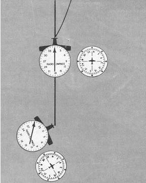
Outbound Tracking. Procedures for tracking outbound are identical to those used for inbound tracking. However, the direction of the azimuth needle deflections are different from those noted during inbound track interceptions, as shown in Figure 8-28. When tracking inbound, a change of heading toward the desired track results in movement of the azimuth needle toward zero. When tracking outbound, a change of heading toward the desired track results in needle movement further away from the 180° position.
Time/Distance Checks (ADF). Time and distance to a station may be calculated with radio-compass procedures similar to the VOR procedures already discussed. A variety of methods commonly used are variations of the basic procedures that follow.
Wing-Tip Bearing Change. To determine the time/distance to the station, use the following steps:
1. After tuning in the station, determine the relative bearing
from the position of the ADF needle.
2. Turn the number of degrees necessary to place the needle
on 090° or 270°.
3. Note the time, and fly a constant magnetic heading for a
specific number of degrees of bearing change. The amount of change flown
varies with the observed rate of bearing change. For example, a 10°
change at a considerable distance from the station may take unnecessarily
long; the time/distance check can be accomplished in this case by timing
a 5° change.
4. Apply the observed time interval to the formula, or calculate
the time to station by rule of thumb if a 10° bearing change is used
(SEE Time/Distance Checks by VOR). For example, you are flying a magnetic
heading of 180°. TAS 130 knots, ADF relative bearing 090°. Maintaining
the magnetic heading for 4 minutes, you observe a relative bearing of 100°.
Approximate time to station is as follows:
Figure 8-28. ADF tracking-outbound.
 |
|
 |
By formula:
60 x minutes between bearing change
Minutes to station = ------------------------------------
Degrees of bearing change
60 x 4
= -------
10
= 24 minutes
By rule of thumb (for 10° change):
Minutes to station = 6 x time in minutes between bearing
change.
= 6 x 4
= 24 minutes
time in seconds
or Minutes to station = -----------------
10
240
= -----
10
= 24 minutes
To determine the distance from the station, use the formula (see Time/Distance Checks by VOR) or the following computer method:
1. Place the speed index opposite True Air Speed.
2. Read distance from station on miles scale opposite time from
station on minutes scale.
Other time/distance checks are applications of the isosceles
triangle principle:
Bow-to-beam bearing gives time to station by the following steps:
1. Turn the number of degrees necessary to place the ADF needle
on 045° (or 315°).
2. Maintain heading until the needle is on 090° (or 270°).
3. Time/distance flown equals time/distance to station.
The Double-the-angle-on-bow method involves the following steps:
1. Tune in a station between 10° and 45° off the nose
position, and note the relative bearing.
2. Fly a constant magnetic heading until the angle on the nose
doubles.
3. The time/distance required to double the angle on the nose
equals the time/distance to the station.
The accuracy of time/distance checks involves a number of variables, including existing wind, accuracy of timing, and heading control. Time checks, especially those involving a rapid rate of bearing change, demand very precise techniques in basic instrument flying while you maintain heading and check elapsed time.