Basic ADF orientation, tracking, and time/distance procedures
may be applied to the problem of intercepting a specified inbound or outbound
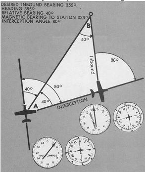
magnetic bearing. To intercept an inbound magnetic bearing, the following
steps may be used (Fig. 8-29):
1. Determine your position in relation to the station by turning
to the magnetic heading of the bearing to be intercepted.
2. Note whether the station is to the right or left of the nose
position. Determine the number of degrees of needle deflection from the
zero position, and double this amount for the interception angle.
Figure 8-29. Interception of predetermined magnetic bearing.
|
3. Turn the aircraft toward the desired magnetic bearing the
number of degrees determined for the interception angle.
4. Maintain the interception heading until the needle is deflected
the same number of degrees from the zero position as the angle of interception
(minus lead appropriate to the rate of bearing change).
5. Turn inbound and continue with tracking procedures.
Note that this method combines inbound course interception with
a time estimate to the station, since the interception leg and the inbound
leg are equal sides of an isosceles triangle. The time from the completion
of the turn to the interception heading (075°) until interception of
the desired inbound bearing is equal to the time-to-station (double-the-angle-on-bow).
Interception of an outbound magnetic bearing can be accomplished
by the same procedures as for the inbound intercept, except that you substitute
the 180° position for the zero position on the azimuth needle.
Application of Basic ADF Procedures
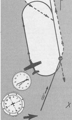
Assume that you have departed airport "X" to fly direct to a
destination airport via an inbound magnetic bearing of 020° to the
"H" facility located on the airport. See Figure 8-30.
Figure 8-30. Application of ADF procedures.
 |
|
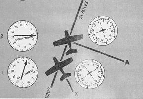 |
1. You intercept the desired inbound magnetic bearing at a 45°
angle and establish the inbound track with a 10° left drift correction
angle, heading 010°.
2. Plotting Position. Tuning in nondirectional beacon "A", note
the time as the ADF needle indicates 100°. With a 10° left drift
correction angle, your position is 90° to the station. The fix can
be directly located on the inbound track line drawn on your aeronautical
chart. Move your plotter along the track line until the 090 reference line
intersects the station.
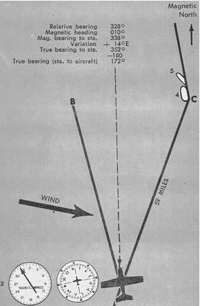
3. You establish another fix by tuning in non-directional beacon
at "B", noting 9 minutes elapsed time as the ADF shows a relative bearing
of 328°. Adding the relative bearing and magnetic heading, the magnetic
bearing to the station is 338°. To plot the fix on your chart, the
magnetic bearing must be converted to a true bearing FROM the station.
Assuming 14° E variation, the true bearing from the station is 172°,
which fixes your position 21 nautical miles from the one established 9
minutes earlier. From this data you compute groundspeed as 140 knots and
estimate arrival time at your destination after measurement of the remaining
distance.
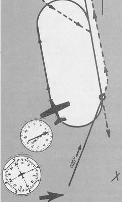
4. Holding should be accomplished in the pattern depicted on
the chart unless ATC instructs you otherwise. The depicted holding pattern
will normally be aligned with the final approach course to the airport
to facilitate letdown and approach to the field. The ADF approach combines
the basic procedures you have already studied - orientation, tracking inbound
and outbound, and interception of predetermined bearings.
Figure 8-31 illustrates a standard holding pattern (dotted line shows holding entry), as well as the procedure turn for approach to the airport. Holding may or may not be necessary, depending upon traffic and weather conditions. If you hold as illustrated, your entry would be as specified in the Airman's Information Manual. The appropriate communications procedures are explained in a later chapter of this text. Assuming a 10° left drift correction angle as you track inbound on the 020° magnetic bearing, proceed as follows:
a. Turn parallel the outbound course as the ADF needle
indicates station passage, applying drift correction appropriate to the
known wind. Note the time.
b. Fly the outbound heading for approximately one minute,
observing the ADF needle for drift toward, or away from, the inbound holding
course. If you apply a 10° left drift correction angle, drift away
from course will be shown by movement of the needle farther from the 180°
position or by failure of the needle to move toward the tail position as
you proceed outbound.
c. Turn toward the inbound course, rolling out on a 125°
magnetic heading for a 45° interception of the inbound course. Note
the relative bearing immediately. If it is greater than 045°, you have
overshot the inbound course and may have difficulty establishing the track
before passing the station.
d. Lead the turn to the inbound course (170°) and
roll out with drift correction. If you are on course, your drift correction
angle will be equal and opposite to the ADF needle displacement from zero.
e. Track inbound, using small corrections. The quicker
you establish the desired track, the fewer your holding problems since
both basic flight techniques and procedural details will keep you busy.
f. Turn outbound on station passage, noting the time.
With no wind, timing the outbound leg would begin as you roll out on a
350° heading with the ADF needle reading 090°. With the wind as
shown, your track would be closer to the station than shown in the diagram.
g. Roll out on an outbound heading with a drift correction
angle equal to double the amount of inbound drift correction. As you begin
outbound timing for one minute, your ADF will indicate approximately 110°,
assuming a 20° left drift correction angle. As you maintain the outbound
heading, the needle moves toward the 180° position. With experience,
you learn to recognize drift by rate of movement of the ADF needle - rapidly
toward the tail position if you drift inward or a strong tailwind exists;
slowly toward the tail if you drift outward or a strong headwind exists.
h. With correct inbound and outbound drift correction
angles, your ADF should read zero, plus or minus the appropriate drift
correction angle, as you complete the turn to track inbound.
i. The approach is normally begun directly from the holding
pattern, tracking inbound as you descend and execute a low approach to
the field.
5. Procedure Turn and Low Approach. When a final approach from
a nondirectional beacon holding pattern is not authorized, a procedure
turn is required for course reversal. For execution of the procedure turn
and approach shown in Figure 8-31, the approach procedure depicted on the
approach chart for the airport would be used. At this point, you are concerned
with the application of basic navigational techniques to the problem. The
associated procedures are shown on the illustration.
To track outbound and reverse course to the final approach, proceed
as follows:
a. On station passage, note the time, and turn outbound to intercept
the 350° magnetic bearing.
b. Start the procedure turn to 305° as soon as practicable,
normally within 2 minutes of station passage. Hold the 305° heading
for 40 seconds to 1 minute, depending upon the existing wind.
c. Turn inbound to intercept and track the 170° magnetic
bearing to the field.
The suggestions discussed earlier with respect to station approach are of particular importance during the low approach. An ADF instrument approach executed without additional navigation airborne equipment or radar assistance demands a high level of skill in the use of both basic flight and navigation instruments, as well as facility with communications procedures. It is essential that you be thoroughly familiar with courses, altitudes, and procedural details well before you execute the approach in order that you be able to visualize the details in their necessary sequence.
Figure 8-31. Transition to ADF approach.
 |
|
 |
1. Check radio contact with Air Traffic Control before arrival over
station. Maintain assigned altitude, or if cleared for approach, descend
to initial approach altitude.
2. Turn outbound, reduce speed if necessary, note time, report station
passage to ATC, and perform prelanding check.
3. Descend to procedure turn altitude given on approach chart.
4. Procedure turn in direction shown on approach chart.
5. Inbound, descend to minimum altitude over final approach fix, then
to MDA.
6. Inbound, report over final approach fix and complete approach to
landing. If field is below minimums, report and execute missed approach
depicted an approach chart, or as directed by ATC.
Common Errors in the use of Navigation Instruments
Other than the specific errors outlined below, the errors underlying most confusion while learning navigation techniques relate to skill in the use of basic flight instruments. You cannot read a VOR or ADF indication while you fumble with pitch, bank, power, and trim control any more than you can read a highway sign or follow a cloverleaf intersection while you stare at your automobile brake pedal.
Mastery of basic flight maneuvers is prerequisite to their application on the aerial highways.
VOR Errors
1. Careless tuning and identification of station.
2. Failure to check receiver for accuracy/sensitivity.
3. Turning in the wrong direction during an orientation. This
error is common until you visualize position rather than heading.
4. Failure to check the ambiguity indicator, particularly during
course reversals, with resulting "reverse sensing" and corrections in the
wrong direction.
5. Failure to parallel the desired radial on a track interception
problem. Without this step, orientation to the desired radial can be confusing.
Since you think in left/right terms, aligning your aircraft position to
the radial/course is essential.
6. Incorrect rotation of the course-selector (OBS) on a time/distance
problem.
7. Overshooting and undershooting radials on interception problems.
Factors affecting lead should be thoroughly understood, especially on close-in
course interception.
8. Overcontrolling corrections during tracking, especially close
to the station.
9. Misinterpretation of station passage. On VOR receivers equipped
without an ON/OFF flag, a voice communication on the VOR frequency will
cause the same to/from fluctuations on the ambiguity meter as shown on
station passage. Read the whole receiver - TO/FROM, CDI, and OBS - before
you make a decision.
10. Chasing the CDI, resulting in homing instead of tracking.
Careless heading control and failure to bracket wind corrections makes
this error common.
ILS Errors
1. Failure to understand the fundamentals of ILS ground equipment,
particularly the differences in course dimensions. Since the VOR receiver
is used on the localizer course, the assumption is sometimes made that
interception and tracking techniques are identical when tracking localizer
courses and VOR radials. Remember that the CDI sensing is sharper and faster
on the localizer course.
2. Disorientation during transition to the ILS due to poor planning
and reliance on one receiver instead of on all available airborne equipment.
Use all the assistance you have available; the single receiver you may
be relying on may fail you at a busy time.
3. Disorientation on the localizer course, basically due to the
first error noted above.
4. Incorrect localizer interception angles. A large interception
angle usually results in overshooting and often disorientation. Turn to
the localizer course heading immediately upon the first indication of needle
movement, using a small interception angle whenever possible. An ADF receiver
is an excellent aid to orientation during an ILS approach.
5. Chasing the CDI and glide path needles, especially when the
approach is not sufficiently studied before the flight. Flying the proper
headings, altitudes, rate of descent, times and power configuration settings
is impossible if your mind is on studying the approach chart.
ADF Errors
1. Improper tuning and station identification. Homing or tracking
to the wrong station has been done by many students.
2. Dependence on homing rather than proper tracking, commonly
results from reliance on the ADF indications instead of correlating them
with heading indications.
3. Poor orientation, due to failure to follow proper steps in
orientation and tracking.
4. Careless interception angles, very likely if you rush the
initial orientation procedure.
5. Overshooting and undershooting predetermined magnetic bearings,
often due to forgetting the course interception angles used.
6. Failure to maintain selected headings. Any heading change
is accompanied by an ADF needle change. The instruments must be read in
combination before any interpretation is made.
7. Failure to understand the limitations of the radio compass
and the factors that affect its use.
8. Overcontrolling track corrections close to the station (chasing
the ADF needle), due to failure to understand or recognize station approach.
9. Failure to keep heading indicator set with magnetic compass.