Clearance Shorthand
The shorthand system given here is recommended by the Federal
Aviation Administration. Applicants for the Instrument Rating may use any
shorthand system, in any language, which ensures accurate compliance with
ATC instructions. No shorthand system is required by regulation and no
knowledge of shorthand is required for the written test; however, because
of the vital necessity for safe coordination between the pilot and controller,
clearance information should be unmistakably clear.
As an instrument pilot, you should make a written record of all
ATC clearances and instructions that consist of more than a few words;
and any portions that are complex, or about which there is any doubt, should
be verified by a repeat back. Safety demands that you receive correctly
and do not forget any part of your clearance.
Occasionally ATC will issue a clearance that differs from the original request. In such cases, the pilot must be particularly alert to be sure that he receives and understands the clearance given.
The following symbols and contractions represent words and phrases
frequently used in clearances. Most of them are regularly used by ATC personnel.
Learn them along with the location identifiers which you will use.
By using this shorthand, omitting the parenthetical words, you
will be able, after some practice, to copy long clearances as fast as they
are read.
WORDS AND PHRASES SHORTHAND
ABOVE - - - - - - - - - - - - - - - - - - - - - - - - - - - -
ABV
ABOVE (ALTITUDE--HUNDREDS OF FEET) - - - - - - - - - - - - - -
70
ADVISE - - - - - - - - - - - - - - - - - - - - - - - - - - - -
ADV
AFTER (PASSING) - - - - - - - - - - - - - - - - - - - - - - -
<
AIRWAY (DESIGNATION) - - - - - - - - - - - - - - - - - - - - -
V26
AIRPORT - - - - - - - - - - - - - - - - - - - - - - - - - - -
A
ALTERNATE INSTRUCTIONS - - - - - - - - - - - - - - - - - - - -
( )
ALTITUDE 6,000 - 17,000 - - - - - - - - - - - - - - - - - - -
60-170
AND - - - - - - - - - - - - - - - - - - - - - - - - - - - - -
&
APPROACH - - - - - - - - - - - - - - - - - - - - - - - - - - -
AP
APPROACH CONTROL - - - - - - - - - - - - - - - - - - - - - - -
APC
AT - - - - - - - - - - - - - - - - - - - - - - - - - - - - - -
@
(ATC) ADVISES - - - - - - - - - - - - - - - - - - - - - - - -
CA
(ATC) CLEARS OR CLEARED - - - - - - - - - - - - - - - - - - -
C
(ATC) REQUESTS - - - - - - - - - - - - - - - - - - - - - - - -
CR
BACK COURSE - - - - - - - - - - - - - - - - - - - - - - - - -
BC
BEARING - - - - - - - - - - - - - - - - - - - - - - - - - - -
BR
BEFORE (REACHING,PASSING) - - - - - - - - - - - - - - - - - -
>
BELOW - - - - - - - - - - - - - - - - - - - - - - - - - - - -
BLO
BELOW (ALTITUDE - HUNDREDS OF FEET) - - - - - - - - - - - - -
CENTER - - - - - - - - - - - - - - - - - - - - - - - - - - - -
CTR
CLEARED AS FILED - - - - - - - - - - - - - - - - - - - - - - -
CAF
CLEARED TO LAND - - - - - - - - - - - - - - - - - - - - - - -
L
CLIMB TO (ALTITUDE - HUNDREDS OF FEET) - - - - - - - - - - - -
CONTACT - - - - - - - - - - - - - - - - - - - - - - - - - - -
CT
CONTACT APPROACH - - - - - - - - - - - - - - - - - - - - - - -
CAP
CONTACT (DENVER) APPROACH CONTROL - - - - - - - - - - - - - -
(den
CONTACT (DENVER) CENTER - - - - - - - - - - - - - - - - - - -
(DEN
COURSE - - - - - - - - - - - - - - - - - - - - - - - - - - - -
CRS
CROSS - - - - - - - - - - - - - - - - - - - - - - - - - - - -
X
CRUISE - - - - - - - - - - - - - - - - - - - - - - - - - - - -
DELAY INDEFINITE - - - - - - - - - - - - - - - - - - - - - - -
DLI
DEPART - - - - - - - - - - - - - - - - - - - - - - - - - - - -
DP
DEPARTURE CONTROL - - - - - - - - - - - - - - - - - - - - - -
DPC
DESCEND TO (ALTITUDE - HUNDREDS OF FEET) - - - - - - - - - -
DIRECT - - - - - - - - - - - - - - - - - - - - - - - - - - - -
DR
DIRECTION (BOUND)
EASTBOUND - - - - - - - - - - - - - - - - - - - - - -
- - - EB
WESTBOUND - - - - - - - - - - - - - - - - - - - - - -
- - - WB
NORTHBOUND - - - - - - - - - - - - - - - - - - -
- - - - - NB
SOUTHBOUND - - - - - - - - - - - - - - - - - - -
- - - - - SB
INBOUND - - - - - - - - - - - - - - - - - - - - - - -
- - - IB
OUTBOUND - - - - - - - - - - - - - - - - - - - -
- - - - - OB
DME FIX (MILE) - - - - - - - - - - - - - - - - - - - - - - - -
EACH - - - - - - - - - - - - - - - - - - - - - - - - - - - - -
EA
ENTER CONTROL AREA - - - - - - - - - - - - - - - - - - - - - -
ESTIMATED TIME OF ARRIVAL - - - - - - - - - - - - - - - - - -
ETA
EXPECT - - - - - - - - - - - - - - - - - - - - - - - - - - - -
EX
EXPECT APPROACH CLEARANCE - - - - - - - - - - - - - - - - - -
EAC
EXPECT FURTHER CLEARANCE - - - - - - - - - - - - - - - - - - -
EFC
FAN MARKER - - - - - - - - - - - - - - - - - - - - - - - - - -
FM
FINAL - - - - - - - - - - - - - - - - - - - - - - - - - - - -
F
FLIGHT LEVEL - - - - - - - - - - - - - - - - - - - - - - - - -
FL
FLIGHT PLANNED ROUTE - - - - - - - - - - - - - - - - - - - - -
FPR
FOR FURTHER CLEARANCE - - - - - - - - - - - - - - - - - - - -
FFC
FOR FURTHER HEADINGS - - - - - - - - - - - - - - - - - - - - -
FFH
FROM - - - - - - - - - - - - - - - - - - - - - - - - - - - - -
FR
HEADING - - - - - - - - - - - - - - - - - - - - - - - - - - -
HDG
HOLD (DIRECTION) - - - - - - - - - - - - - - - - - - - - - - -
H-W
HOLDING PATTERN - - - - - - - - - - - - - - - - - - - - - - -
ILS APPROACH - - - - - - - - - - - - - - - - - - - - - - - - -
ILS
INITIAL APPROACH - - - - - - - - - - - - - - - - - - - - - - -
I
INTERSECTION - - - - - - - - - - - - - - - - - - - - - - - - -
XN
JOIN OR INTERCEPT AIRWAY/JET ROUTE/TRACK OR COURSE - - - - - -
LEFT TURN AFTER TAKEOFF - - - - - - - - - - - - - - - - - - -
LOCATOR OUTER MARKER - - - - - - - - - - - - - - - - - - - - -
LOM
MAINTAIN OR MAGNETIC - - - - - - - - - - - - - - - - - - - - -
M
MAINTAIN VFR CONDITIONS ON TOP - - - - - - - - - - - - - - - -
VFR
MIDDLE COMPASS LOCATOR - - - - - - - - - - - - - - - - - - - -
ML
MIDDLE MARKER - - - - - - - - - - - - - - - - - - - - - - - -
MM
NONDIRECTIONAL BEACON APPROACH - - - - - - - - - - - - - - - -
NDB
OUT OF (LEAVE) CONTROL AREA - - - - - - - - - - - - - - - - -
OUTER MARKER - - - - - - - - - - - - - - - - - - - - - - - - -
OM
OVER (STATION) - - - - - - - - - - - - - - - - - - - - - - - -
OKC
ON COURSE - - - - - - - - - - - - - - - - - - - - - - - - - -
OC
PRECISION RADAR APPROACH - - - - - - - - - - - - - - - - - - -
PAR
PROCEDURE TURN - - - - - - - - - - - - - - - - - - - - - - - -
PT
RADAR VECTOR - - - - - - - - - - - - - - - - - - - - - - - - -
RV
RADIAL (080° RADIAL) - - - - - - - - - - - - - - - - - - - - -
080R
REMAIN WELL TO LEFT SIDE - - - - - - - - - - - - - - - - - - -
LS
REMAIN WELL TO RIGHT SIDE - - - - - - - - - - - - - - - - - -
RS
REPORT CROSSING - - - - - - - - - - - - - - - - - - - - - - -
RX
REPORT DEPARTING - - - - - - - - - - - - - - - - - - - - - - -
RD
REPORT LEAVING - - - - - - - - - - - - - - - - - - - - - - - -
RL
REPORT ON COURSE - - - - - - - - - - - - - - - - - - - - - - -
R-CRS
REPORT OVER - - - - - - - - - - - - - - - - - - - - - - - - -
RO
REPORT PASSING - - - - - - - - - - - - - - - - - - - - - - - -
RP
REPORT REACHING - - - - - - - - - - - - - - - - - - - - - - -
RR
REPORT STARTING PROCEDURE TURN - - - - - - - - - - - - - - - -
RSPT
REVERSE COURSE - - - - - - - - - - - - - - - - - - - - - - - -
RC
RIGHT TURN AFTER TAKEOFF - - - - - - - - - - - - - - - - - - -
RUNWAY (NUMBER) - - - - - - - - - - - - - - - - - - - - - - -
RY18
SQUAWK - - - - - - - - - - - - - - - - - - - - - - - - - - - -
SQ
STANDBY - - - - - - - - - - - - - - - - - - - - - - - - - - -
STBY
STRAIGHT-IN APPROACH - - - - - - - - - - - - - - - - - - - - -
SI
SURVEILLANCE RADAR APPROACH - - - - - - - - - - - - - - - - -
ASR
TAKEOFF (DIRECTION) - - - - - - - - - - - - - - - - - - - - -
TOWER - - - - - - - - - - - - - - - - - - - - - - - - - - - -
Z
UNTIL - - - - - - - - - - - - - - - - - - - - - - - - - - - -
U
UNTIL ADVISED (BY) - - - - - - - - - - - - - - - - - - - - - -
UA
UNTIL FURTHER ADVISED - - - - - - - - - - - - - - - - - - - -
UFA
VIA - - - - - - - - - - - - - - - - - - - - - - - - - - - - -
VIA
VICTOR (AIRWAY NUMBER) - - - - - - - - - - - - - - - - - - - -
V14
VISUAL APPROACH - - - - - - - - - - - - - - - - - - - - - - -
VA
VOR - - - - - - - - - - - - - - - - - - - - - - - - - - - - -
VORTAC - - - - - - - - - - - - - - - - - - - - - - - - - - - -
WHILE IN CONTROL AREA - - - - - - - - - - - - - - - - - - - -
EXAMPLE
An example of a clearance written in shorthand:
CAF M RY HDG RV V18 SQ 0700 DPC 120.4
Translated it reads: (Aircraft number), cleared as filed, maintain runway heading for radar vector to Victor 18, squawk 0700 just before departure, departure control frequency - 120.4.
Supplementary Reference Material
Persons studying for the instrument rating, as well as qualified instrument rated pilots, will find the publications and materials listed below to be useful in augmenting their knowledge of instrument flying. In addition to these, there are many excellent textbooks, charts, and other reference materials available from commercial publishers.
Advisory Circulars and Flight Information Publications
ADVISORY CIRCULARS
00-6A - Aviation Weather
Provides an up-to-date and expanded text for pilots and other
flight operations personnel whose interest in meteorology is primarily
in its application to flying. (Supt. Docs.)
00-45B - Aviation Weather Services
Supplements AC 00-6A, Aviation Weather, in that it explains the
weather service in general and the use and interpretation of reports, forecasts,
weather maps, and prognostic charts in detail. It is an excellent source
of study for pilot certification examinations. (Supt. Docs.)
61-8D - Instrument Rating Written Test Guide
Reflects the current operating procedures and techniques in a
background setting appropriate for applicants preparing for the Instrument
Pilot Airplane and Instrument Pilot Helicopter written tests. (Supt. Docs.)
61-56A - Flight Test Guide - Instrument Pilot Airplane
Assists the applicant and the instructor in preparing for the
flight test for the Instrument Pilot Airplane Rating. (Supt. Docs.)
61-64A - Flight Test Guide - Instrument Pilot Helicopter
Assists the applicant and the instructor in preparing for the
Instrument Pilot Helicopter Rating. (Supt. Docs.)
91-23A - Pilot's Weight and Balance Handbook
Provides an easily understood text on aircraft weight and balance
for pilots who need to appreciate the importance of weight and balance
control for safety of flight. Progresses from an explanation of basic fundamentals
to the complete application of weight and balance principles in large aircraft
operations. (Supt. Docs.)
In addition, the following Advisory Circulars pertain to areas of knowledge listed in the "Study Outline" and are available from FAA free of charge: 00-24A, 20-32B, 60-4, 60-6A, 91-8A {Canceled by AC 61-107 - Ed.}, and 91-25A.
FLIGHT INFORMATION
Airman's Information Manual (AIM) Basic Flight Information and
ATC Procedures. Issued semi-annually, January and July.
Graphic Notices and Supplemental Data. Issued quarterly.
Notices to Airmen (Class II). Issued every 14 days.
Descriptions of the contents, source of supply, prices and stock
numbers where applicable, for all Advisory Circulars and the other flight
information publications listed above, are contained in AC 00-2, Advisory
Circular Checklist available free of charge from:
U.S. Department of Transportation
Publications Section, M-443.1
Washington, D.C. 20590
IFR and VFR Pilot Exam-o-Grams
These brief instructional aids are prepared on subject areas
in which applicants for airman written examinations have shown a lack of
knowledge. They are an excellent media for providing guidance information
to applicants preparing for the various written tests.
Exam-O-Grams may be obtained from:
Superintendent of Documents
U.S. Government Printing Office
Washington, D.C. 20402.
FEDERAL AVIATION REGULATIONS (FARs)
Part 1. Definitions and Abbreviations.
Part 61. Certification: Pilots and Flight Instructors.
Part 91. General Operating and Flight Rules.
Part 95. IFR Altitudes.
Part 97. Standard Instrument Approach Procedures.
Federal Aviation Regulations are sold by the Superintendent of Documents. AC 00-44, Status of Federal Aviation Regulations, lists the FAR Parts, their Changes, prices, stock numbers, and ordering information. AC 00-44 is available free of charge from:
U.S. Department of Transportation
Publications Section, M-443.1
Washington, D.C. 20590
If you wish to be placed on the free mail list to receive revised copies of either AC 00-2 or AC 00-44, send your name and address to:
U.S. Department of Transportation
Distribution Requirements Section, M-482.2
Washington, D.C. 20590
Aeronautical Charts and Airport/Facility Directory
Enroute Low and High Altitude Charts. These charts provide necessary
aeronautical information for enroute instrument navigation in the established
airway structure.
Area Charts. These charts are part of the Enroute Low Altitude
Chart series. They furnish terminal data on a larger scale in congested
areas.
Instrument Approach Procedures Charts. Each of these charts depict
an instrument approach procedure, including all related data, and the airport
diagram.
Standard Instrument Departures (SIDs). These charts are collated
in two booklets, "East" and "West." They are designed for use with Enroute
Low and High Altitude and Area Charts. They furnish pilots departure routing
clearance in graphic and textual form.
Standard Terminal Arrival Routes (STARs). These charts are collated
in one booklet and are designed for use with Enroute Low and High Altitude
Charts. They furnish pilots preplanned instrument flight rules (IFR) air
traffic control arrival route procedures in graphic and textual form. The
National Ocean Survey publishes and distributes the Airport/Facility Directory
and aeronautical charts of the United States. Charts for foreign areas
are published by the U.S. Air Force Aeronautical Chart and Information
Center (ACIC) and are sold to civil users by the National Ocean Survey.
A "Catalog of Aeronautical Charts and Related Publications,"
listing their prices and instructions for ordering, may be obtained free
on request from:
Department of Commerce
National Ocean Survey
Distribution Division (C-44)
Riverdale, Maryland 20840
Orders for the Airport/Facility Directory and for specific charts or publications should be accompanied by check or money order made payable to, NOS, Department of Commerce.
Study Outline for the Instrument Pilot Written Test
This study outline covers the areas of aeronautical knowledge which pertain to Instrument Pilot Written Tests. The outline expands the general aeronautical knowledge requirements set forth in Federal Aviation Regulations Part 61, and is based on airman activity for flight under Instrument Flight Rules.
REFERENCE CODE:
AC - Advisory Circular
AW - Aviation Weather (AC 00-6A)
AWS - Aviation Weather Services (AC 00-45B)
AIM - Airman's Information Manual
AFD - Airport/Facility Directory
NOTAM - Notices to Airmen
EOG - IFR Exam-O-Grams
IFH - Instrument Flying Handbook (AC 61-27C)
BHH - Basic Helicopter Handbook (AC 61-13B)
IAPC - Instrument Approach Procedure Charts
PHB - Pilot's Handbook of Aeronautical Knowledge (AC 61-23B)
I. FLIGHT PLANNING
A. Certificates and Ratings
1. Requirements for certificates and ratings (61.3)
2. Eligibility for instrument rating (61.65)
3. Where instrument rating required (61.3(e), 91.97 {§
91.97 recodified to § 91.135})
4. Recency of experience (61.57)
B. Preflight Action for Flight
1. Familiarization with all available information (91.5 {§
91.5 recodified to § 91.103}; EOG-31; AFD)
2. Fuel requirements (91.23 {§ 91.23 recodified to §
91.167})
C. Preflight Action for Aircraft (EOG-31)
1. Responsibility for airworthiness (91.29 {§ 91.29 recodified
to § 91.7})
2. Equipment required
Instruments and equipment (91.33 {§ 91.33 recodified
to § 91.205})
Transponder (91.24 {§ 91.24 recodified to §
91.215}, 91.90 {§ 91.90 recodified to § 91.131})
ELT (91.52 {§ 91.52 recodified to § 91.207})
3. Tests and inspections
VOR (91.25 {§ 91.25 recodified to § 91.171};
EOG-22; AIM)
Altimeter system (91.170 {§ 91.170 recodified to
§ 91.415})
Transponder (91.177)
Aircraft (91.169 {§ 91.169 recodified to § 91.409})
4. Portable electronic devices (91.19 {§ 91.19 recodified
to § 91.21})
D. Flight Plan (AIM)
1. When required (91.97 {§ 91.97 recodified to § 91.135},
91.115 {§ 91.115 recodified to § 91.173})
2. Information required (91.83 {§ 91.83 recodified to §
91.153})
3. Alternate airport requirements (91.83 {§ 91.83 recodified
to § 91.153})
E. Route Planning
1. Preferred routes (AFD); SIDs and STARs; Enroute Charts
2. Airport/Facility Directory
3. NOTAM
4. FDC NOTAMs (NOTAM)
5. Special Notices (NOTAM, AFD)
6. Area Navigation Routes (NOTAM)
7. Direct Routes (AIM, Airspace; 91.119 {§ 91.119 recodified
to § 91.177}, 91.121(b) {§ 91.121 recodified to § 91.179})
8. Restrictions to Enroute Nav. Aids (AFD)
9. Substitute Route Structure (EOG-39)
F. Flight Planning (Ch. XIII-IFH)
1. Wind correction angle - heading
2. GS
3. ETE/ETA
4. Fuel estimates
G. Aircraft Performance (Aircraft Owner's Handbook; VFR EOG-33;
EOG-32)
1. Takeoff distance
2. Climb performance
3. Cruise performance (VFR EOG-38)
4. Fuel flow
5. Landing performance
6. Airspeed: IAS, CAS, EAS, TAS
7. Placards and instrument markings
8. Hovering
H. Aircraft Operating Limitations (documents in aircraft, AC
60-6A)
1. Weight and balance (EOG-21; AC 91-23A)
2. Instrument limit markings and placards (91.31 {§ 91.31
recodified to § 91.9})
3. Maximum safe crosswind (VFR EOG-27)
4. Turbulent air penetration
I. Aircraft Systems (Ch. IV-IFH)
1. Pitot-static system (EOG-10; IFH)
2. Vacuum/gyroscopic (EOG-24)
3. Electric/gyroscopic
4. Compass
J. Fundamentals of Weather
1. Composition of the atmosphere (Ch. I-AW)
2. Temperature (Ch. 2-AW)
3. Pressure (Ch. 3-AW)
4. Circulation (Ch. 4-AW)
5. Moisture (Ch. 5-AW)
6. Stability and wind (Ch. 6-AW)
7. Clouds (Ch. 7-AW)
8. Air masses and fronts (Ch. 8-AW)
9. Turbulence (Ch. 9-AW)
K. IFR Weather Hazards
1. Icing (Ch. 10-AW)
2. Thunderstorms (Ch. 11-AW; AIM)
3. Fog and obstructions to vision (Ch. 12-AW)
L. Aviation Weather Observations and Reports
1. Aviation weather reports (SA) (AWS-2)
2. Pilot weather reports (PIREPs, UA) (AWS-3)
3. Radar weather reports (RAREPs) (AWS-3) Radar summary chart
AWS-7)
4. Surface analysis (AWS-5)
5. Weather depiction chart (AWS-6)
6. Upper wind chart (AWS-9)
7. Freezing level chart (AWS-10)
8. Stability chart (AWS-11)
9. Constant pressure charts (AWS-13)
M. Aviation Weather Forecasts
1. Terminal (FT) (AWS-4; EOG-5)
2. Area (FA) (AWS-4; EOG-5)
3. Winds and temperatures aloft (FD) (AWS-4) and chart (AWS-9)
4. Severe weather (AWS-4), Hurricane advisories (WH); convective
outlook (AC); Weather Watch (WW); severe weather outlook chart (AWS-12)
5. TWEB route forecast and synopsis (AWS-4)
6. Inflight advisories (WS, WA, WAC) (AWS-4)
7. Prognostic charts: Surface (AWS-8); Significant Weather (AWS-8);
Constant Pressure (AWS-14); Tropopause and Wind Shear (AWS-15)
N. Weather Tables and Conversion Graphs (AWS-16)
1. Icing intensities
2. Turbulence intensities
3. Locations of probable turbulence
4. Standard temperature, speed, and pressure conversions
5. Density altitude
O. Weather Facilities
1. FSS weather service (AFD; EOG-19), Telephone numbers (AFD),
Remote weather radar display (AFD), Scheduled weather broadcast (AFD)
2. ATIS (AIM)
3. Weather Service Forecast Offices (AIM); TWEB, PATWAS (AFD)
II. DEPARTURE
A. Authority and Limitations of Pilot
1. Pilot in command (91.3, 91.4 {§ 91.4 recodified to §
91.5}, 91.67 {§ 91.67 recodified to § 91.113}, 91.75 {§
91.75 recodified to § 91.123}, 91.87(h) {§ 91.87 recodified to
§ 91.129})
2. Emergency action (92.3(b) {§ 92.3 does not exist}),
Deviation from rules
3. Required reports, Emergency deviation (91.3(c), 91.75(c)
{§ 91.75 recodified to § 91.123}), Malfunction of equipment (91.33(c)
{§ 91.33 recodified to § 91.205}, 91.129 {§ 91.129 recodified
to § 91.187})
B. Flight Plan
1. Where to file (AFD)
2. When to file (AIM - Flight Plan)
C. Departure Clearance (AIM - Departures; EOG-35)
1. "Cleared as filed"
2. Amended clearance
3. Pretaxi clearance procedure
4. Clearance delivery (AFD)
D. Taxi and Takeoff Procedures (AIM - Departure and Airport Operation)
1. Taxi limits (AIM; EOG-26, 28)
2. ATC control sequence (AIM)
3. Airport advisory service (AIM; AFD)
4. ATIS (AIM; AFD)
E. Departure Procedures (AIM)
1. Obstruction clearance minimums (approach chart book)
2. Departure control procedures (nonradar)
3. Departure control procedures (radar)
4. SIDs
5. Speed adjustments
6. Terminal area limitations
F. VOR Accuracy Check (AIM; EOG-22; 91.25 {§ 91.25 recodified
to § 91.171})
1. VOT (AFD, L-chart legend)
2. VOR ground checkpoints (AFD)
3. VOR airborne checkpoints (AFD)
4. VOR dual receiver check
G. Pretakeoff Instrument Check (IFH; AC 91-46)
1. Prestart instrument indications
2. Taxi test
H. Transponder (EOG-25; AIM)
1. Operation
2. Switching code
3. Emergency use
I. Airport Facilities (AFD, NOTAM, Charts)
1. Service (AFD, NOTAM)
2. Runways (EOG-26, 28; AIM)
3. Airport lighting (AIM; EOG-33)
4. Communications (AFD)
J. FSS Facility (AIM; EOG-39; chart legend)
1. Flight plan service
2. Traffic advisories (AFD)
3. Communications (AFD)
4. Weather advisories (AFD; AWS-1)
K. Departure Control Facility
1. Communications (AFD; IAPC)
2. Geographical area
III. ENROUTE
A. Enroute Limitations (AIM)
1. Altitude limitations (91.119 {§ 91.119 recodified to
§ 91.177}; EOG-8): MEA, MOCA, MCA, MRA, MAA
2. Cruising altitudes (91.121 {§ 91.121 recodified to §
91.179}, 91.109 {§ 91.109 recodified to § 91.159})
3. Courses to be flown (91.123 {§ 91.123 recodified to
§ 91.181}, 91.67 {§ 91.67 recodified to § 91.113})
4. Altimeter settings (91.81 {§ 91.81 recodified to §
91.121})
5. Positive Control Airspace (91.97 {§ 91.97 recodified
to § 91.135})
6. Special Use Airspace (91.95 {§ 91.95 recodified to §
91.133}; AIM; Enroute Chart)
B. Enroute Procedures (AIM; Ch. XI-IFH)
1. Radar environment - vectors, reporting, handoffs
2. Nonradar environment - reporting, handoffs
3. Altitude: cruise, maintain, climb, descend, VFR on top
4. Delays: clearance limits, holding
5. Securing weather info (AWS-1)
C. ATC Clearances
1. Phraseology (Ch. IX-IFH; AIM; EOG-11, 34, 35)
2. Responses and readbacks (AIM; 91.125 {§ 91.125 recodified
to § 91.183})
D. Oxygen Requirements (91.32 {§ 91.32 recodified to §
91.211})
1. Pilot and crew requirements
2. Passenger requirements
E. Emergencies (AIM; EOG-2)
1. Difficultly with communications
2. Malfunction of equipment
3. LOC (EOG-7 & 14)
4. RNAV (EOG 30)
5. Lost
6. Lost communications (91.127 {§ 91.127 recodified to
§ 91.185}; EOGs 36, 37, 38)
7. Malfunction reports (91.129 {§ 91.129 recodified to
§ 91.187}, 91.33(e) {§ 91.33 recodified to § 91.205})
8. Deviation from clearance (91.75(c) {§ 91.75 recodified
to § 91.123})
F. Radio Orientation (Ch. VIII-IFH)
1. VOR (EOG-7 & 14)
2. NDB (EOG-23)
G. Establishing Radio Fixes and Waypoints (Ch. VIII-IFH)
1. VOR radials
2. VOR-DME (Ch. VII-IFH; AC 90-62; AC 170-3B)
3. ADF (EOG-23)
4. ADF-VOR/LOC
5. RNAV (EOG-30)
H. Enroute Computer Operations
1. GS
2. ETE/ETA
3. Altitude or speed conversion
4. Fuel
I. Attitude Instrument Flying (Ch. V and VI-IFH; AC 91-43)
1. Interpretation of flight instruments
2. Aircraft control: pitch, bank, power
3. Basic maneuvers: straight and level, climbs and descent,
turns (EOG-18)
4. Unusual attitudes
5. Flight patterns
J. Unusual Flight Conditions
1. Thunderstorms (AC 00-24; page 105-AW)
2. Structural icing (Ch. 10-AW)
3. Induction icing (Ch. 10-AW; PHB)
4. Use of anti/deicing equipment
5. Frost
6. Clear air turbulence
K. Radio Navigation Facilities (Ch. VIII-IFH; AIM)
1. VOR/VORTAC
2. NDB
3. LOC
4. DF
5. RADAR
L. Airway Route System (Enroute Chart Legend; AIM; EOG-8)
1. Victor/jet airway limits
2. Route identification: military, substitute, unusable
3. Altitude limits: MOCA, MEA, MRA, MCA, MAA
4. Reporting points: compulsory, noncompulsory
5. Fixes, waypoints
6. Geographical limit: VOR changeover points, altimeter setting
boundary, time zone boundary
7. Airspace designation
M. Special Use Airspace (AIM, chart legends)
1. Prohibited area
2. Restricted area
3. Military operations area
4. Warning area
5. Alert area - intensive student jet training area
N. ARTCC Facility (Ch. XI-IFH; AIM)
1. ARTCC remote frequencies (Enroute Chart)
2. Geographical area of control (Enroute Chart)
3. Advisories, services, assistance
O. Enroute Weather Services (AFD)
1. EFAS (AWS-1)
2. TWEB (AWS-1)
3. ARTCC significant weather advisories
P. Fixed-Wing Aerodynamic Factors (Ch. III-IFH; AC 61-23B)
1. Aerodynamic forces
2. Straight and level
3. Turns
4. Climbs
5. Descents
6. Stalls
Q. Rotary-Wing Aerodynamic Factors (BHH)
1. Vibrations (Ch. 2)
2. Dissymmetry of lift (Ch. 2)
3. Translation (Ch. 2)
4. Rotor disc-loading, coning, and flapping (Ch. 9)
5. Settling with power (Ch. 9)
6. Ground resonance (Ch. 9)
7. Speed limitations (Ch. 9)
8. Autorotation particulars (Ch. 11)
9. Factors affecting performance (Ch. 11)
R. Physiological Factors (Ch. II-IFH; AIM)
1. Physiologic altitude effects: hypoxia, aerotitis, aerosinusitis
(AC 91-8A {Canceled by AC 61-107 - Ed.})
2. Hypoxic effects: alcohol, hyperventilation, drugs, carbon
monoxide (AC 20-32B)
3. Sensations of instrument flying (AC 60-4)
4. Spatial disorientation (AC 60-4)
IV. ARRIVAL
A. Approach Control (AIM; Ch. XII-IFH)
1. Radar control: STARs, Vectors, approach clearances
2. Non-radar control
3. Aircraft speed (91.70 {§ 91.70 recodified to §
91.117})
4. Procedure turns/holding patterns
5. Visual and contact approaches
B. Holding Procedures (AIM)
1. Holding pattern entry
2. Shuttle
3. Changing altitude
4. Timing
5. Adjustments and corrections
C. Precision Approaches (AC 90-1A; IFH; AIM)
1. Initial approach/procedure turn (91.116(h) {§ 91.116
recodified to § 91.175})
2. Vectors to final approach (91.116(f) {§ 91.116 recodified
to § 91.175})
3. Intermediate approach
4. Final approach
5. Glide slope
6. Decision height (91.117(b) {§ 91.117 was deleted when
part 91 was recodified})
7. Inoperative components (91.117(c) {§ 91.117 was deleted
when part 91 was recodified})
8. Reports
D. Non-Precision Approach (AC 90-1A; AIM)
1. Initial approach/procedure turn (91.116(h) {§ 91.116
recodified to § 91.175})
2. Vectors to final approach (91.116(f) {§ 91.116 recodified
to § 91.175})
3. Intermediate approach
4. Final approach
5. Minimum descent altitude (91.117(b) {§ 91.117 was deleted
when part 91 was recodified})
6. Inoperative components (91.117(c) {§ 91.117 was deleted
when part 91 was recodified})
7. Reports
E. Missed Approach (91.117(b) {§ 91.117 was deleted when
part 91 was recodified}; AC 90-1A; AIM)
1. Precision approach
2. Non-precision
3. Loss of visual cues
4. Low approach (practice approaches)
F. Landing Procedures (AIM)
1. Noncontrolled airport (91.89 {§ 91.89 recodified to
§ 91.127})
2. Controlled airport (91.87 {§ 91.87 recodified to §
91.129})
3. Landing minimums (91.116(b) {§ 91.116 recodified to
§ 91.175}, 97.3(d-1))
4. Close flight plan (91.83 {§ 91.83 recodified to §
91.153})
G. Logging of Flight Time
1. Instrument flight time (61.51(4))
2. Conditions for simulated instrument flight (91.21 {§
91.21 recodified to § 91.109})
3. Information required (61.51(4)); Instrument approaches; Safety
pilot
4. Pilot in command (61.51(2))
H. Radio Orientation on Approach (Ch. VIII-IFH)
1. Relation to LOC on front and back course (Ch. VII-IFH; EOG-7)
2. Glide slope (Ch. VII-IFH)
3. LOC and glide slope (EOG-7); Ch. VII-IFH)
4. Marker beacons (Ch. VII-IFH)
5. Compass locators (EOG-23)
6. NDB (EOG-23)
7. VOR/VORTAC (EOG-7)
8. LOC type; LDA, SDF (AIM)
I. Wake Turbulence (AIM; AC 90-23D)
1. Landing hazards
2. Takeoff hazards
3. Inflight hazards
4. Wake turbulence theory
J. Terminal Area (IAPC; AFD)
1. Approach control facility: frequencies, area
2. FSS (AIM): airport advisories, flight plan service, weather
service
K. Instrument Approach Procedure Chart - Planview (AC 90-1A;
IAPC legend)
1. Facility frequencies and services
2. Procedural tracks
3. Fixes and markers
4. Obstructions
5. Special use airspace
6. Radio aids
7. Minimum altitudes
L. Instrument Approach Procedure Chart - Profile (AC 90-1A; IAPC
legend)
1. Altitude limits
2. Descent pattern/glide slope
3. Facilities/fixes
M. Instrument Approach Procedure Chart Aerodrome Sketch (AC 90-1A;
IAPC legend)
1. Runway configuration and specifications
2. Approach light systems
3. Elevations: Obstacles, TDZE, and aerodrome
4. Airport taxi chart
N. Instrument Approach Procedure Chart - Minimums Section (AC
90-1A; IAPC legend)
1. Aircraft category
2. DH/MDA
3. HAT
4. HAA
5. Minimum visibility: miles/RVR
6. IFR takeoff minimums and departure procedures
7. IFR alternate minimums
8. Civil RADAR instrument approach minimums
O. Approach Facilities (AIM; IFH; Chart Legends)
1. ILS
2. LDA
3. SDF
4. VOR/VORTAC
5. NDB
6. Marker beacons, compass locators
7. VASI (91.87(d)(3) {§ 91.87 recodified to § 91.129})
Instrument Flight Instructor Lesson Guide (Airplanes)
U.S. Department of Transportation
Federal Aviation Administration
MIKE MONRONEY AERONAUTICAL CENTER
FAA ACADEMY
Preface
To the Instrument Flight Instructor
The Instrument Flight Instructor Lesson Guide has been prepared
for use with the FAA Instrument Flying Handbook, AC 61-27C. Although the
guide deals with basic instrument flying in airplanes, the instructor can
modify it for use in helicopter instrument training. The seventeen lessons
on Attitude Instrument Flying are arranged in what is considered to be
a logical learning sequence. To ensure steady progress, teach the course
lesson-by-lesson, and be sure the student has mastered each before advancing
to the next. Lessons may be combined when giving refresher training. As
all experienced instrument instructors know, the student will learn more
rapidly during the early stage of instrument training if a considerable
part of the time is spent "open hood." The student is thus allowed to associate
aircraft attitude relative to outside visual references with the indications
of the various flight instruments individually and in combination. This
teaching procedure makes it clear that the pilot uses exactly the same
control techniques during visual and instrument flight: Remember, the largest
single learning factor in Attitude Instrument Flying is that of interpreting
the flight instruments to determine the attitude of the aircraft.
To the Student Instrument Pilot
At the beginning of your instrument flight training, your instructor
will brief you on the concept of Attitude Instrument Flying and explain
each of the flight instruments used in Pitch Control, Bank Control, and
Power Control. Your instructor will point out similarities each instrument
has to outside references and explain the limits and errors inherent in
each instrument. After a thorough demonstration, you will practice using
each instrument individually and in combination with other instruments.
This procedure is followed for the first three lessons on Pitch Control,
Bank Control, and Power Control in level flight. After a short time, you
will be making a logical cross-check and not merely scanning the instruments.
Approximately 6 hours of flight time plus the necessary ground school is
usually required to cover the first three basic lessons. Your instructor
will monitor your progress closely during this early training to guide
you in dividing your attention properly. The importance of this "division
of attention" or "cross-check" cannot be emphasized too much. This, and
proper instrument interpretation, enables the instrument pilot to accurately
visualize the aircraft's attitude at all times. To properly understand
this guide, the terms "Primary Instrument" and "Supporting Instrument"
must be clearly understood. For clarification of these terms, refer to
Chapter V of the FAA Instrument Flying Handbook AC 61-27C.
NOTE: The instrument maneuvers presented in this guide are based
on an airplane equipped with a turn coordinator. If the airplane flown
has a turn needle, the descriptions apply if "turn needle" is substituted
for "miniature aircraft of the turn coordinator." Power settings and airplane
performance figures used in this guide are for illustrative purposes only.
Exact power settings and performance information must be obtained experimentally
or from performance charts for each airplane flown.
Lesson 1
Cockpit Check
1. Publications. Enroute Navigation Charts, Appropriate Pilot's
Handbooks, Terminal Area Charts, Approach Charts, Computer, and Flight
Log.
2. Suction Gauge or Electrical System. For suction-driven gyro
instruments, be sure the suction gauge is within prescribed limits. For
electrically-driven instruments, check generators and inverters for proper
operation.
3. Pitot Head. Cover removed and heat checked.
4. Airspeed Indicator. Check reading, should be zero. Check calibration
card.
5. Heading Indicator. Uncaged, if applicable. Checked against
a known heading, and operating properly
6. Attitude Indicator. Uncaged if applicable. Checked and operating
properly. Set miniature aircraft.
7. Altimeter. Set to current altimeter setting. Check for error.
8. Turn Coordinator. Miniature aircraft operating properly. Ball
moves freely in the race.
9. Vertical-Speed Indicator. Should indicate zero. If it doesn't
and is not adjustable, interpret ground indication as zero.
10. Magnetic Compass. Bowl full of fluid. Card moves freely.
Checked against known heading.
11. Clock. Operating and set to correct time.
12. Carburetor Heat. Check for operation and return to cold position.
13. Engine Instruments. Check for proper markings and readings.
14. Radio Equipment. Checked for proper operation.
15. Trim and Throttle Friction. Trim set for takeoff and throttle
friction adjusted.
16. De-Icing and Anti-Icing Equipment. Check operation.
Pitch Control
1. Attitude Indicator
a. Adjust miniature aircraft for level flight at normal cruise.
b. Demonstrate similarity between the natural horizon and the
horizon bar by placing the nose of the aircraft first above the horizon,
then below it.
c. Discuss the limits of operation.
d. Demonstrate why the attitude indicator must be caged and uncaged
in level flight (if a caging device is available). Stress the importance
of fully uncaging the instrument.
e. Reliable pitch attitude is indicated within approximately
30° in climbs and dives. In excess of 30°, the horizon bar is no
longer visible or may lag. The extreme limits vary with instrument design.
f. Acceleration and deceleration error.
(1) Increase power rapidly from low to high - show loss of altitude
while maintaining a level attitude on the attitude indicator.
(2) Reduce power rapidly from high to low - show gain of altitude
while maintaining a level attitude on the attitude indicator.
(3) Hold altitude during power changes - show that the bar moves
down on acceleration and moves up on deceleration.
g. Comparison of movement of the miniature aircraft and the nose
of the aircraft. The instrument gives a direct indication of pitch.
(1) Adjust the miniature aircraft with the wings exactly centered
on the horizon bar.
(2) Change pitch attitude to 1/2 bar climb - student compares
the movement of the aircraft's nose to the actual horizon.
(3) Change pitch attitude to 1/2 bar descent - student compares
to actual horizon.
(4) Emphasize smooth control pressures and that 1/2 bar is recommended
for small corrections.
h. Student practice.
(1) Maintaining level flight, keeping wings centered on horizon
bar.
(2) Making small pitch changes not to exceed 1/2 bar width.
(3) Place aircraft in moderate climbs and descents and have
student return to level flight.
(4) Stress importance of smoothness and of not overcontrolling.
2. Altimeter
a. Constant altitude.
(1) Maintain straight and level flight at a constant power setting.
Point out that pitch attitude must also remain constant.
(2) Raise the nose of the aircraft until the altimeter indicates
a climb - show the relationship between increased pitch attitude and gain
of altitude.
(3) Lower the nose of the aircraft until the altimeter indicates
a descent show the relationship between decreased pitch and loss of altitude.
b. Determining pitch attitude by the altimeter.
(1) Place the miniature aircraft well above the horizon bar.
Point out the rapid change of the altimeter and the large change of pitch
attitude shown on the attitude indicator.
(2) Make small changes in pitch attitude - show slow change
in altitude. Visualize the approximate change in pitch attitude by interpolating
the rate of altimeter movement.
c. Lag in the altimeter.
(1) Make an abrupt pitch change and point out the momentary
lag in the altimeter.
(2) Make small, smooth pitch changes and point out that the
altimeter, for practical purposes, has no lag.
d. Proper technique for correcting altimeter movement.
(1) Change pitch attitude to stop altimeter.
(2) Change pitch attitude to return smoothly to desired altitude.
e. Cross-check (division of attention) between altimeter and
attitude indicator.
(1) The cross-check is simple. Maintain level flight on the
attitude indicator with frequent reference to the altimeter to determine
that the altitude is being maintained. If an error is noted, correct it
by making an appropriate correction on the attitude indicator. Guard against
over controlling.
(2) During level flight, the altimeter is primary for pitch
and all changes in pitch are made so as to maintain a constant altitude.
f. Student practice.
(1) Maintaining a constant altitude.
(2) Maintaining level flight by use of the attitude indicator
and altimeter.
(3) Lose or gain 50 feet by changing pitch attitude not more
than 1/2 bar (emphasize small pitch changes).
(4) Return to the original altitude, using the above technique.
(5) Repeat this exercise until the student has acquired the
proper cross-check and control technique.
3. Vertical-Speed Indicator
Point out that the instrument reads zero when a constant altitude
is maintained. The vertical-speed indicator is used both as a trend and
a rate instrument.
a. Use of the vertical-speed indicator as a trend instrument.
Observe the vertical-speed indicator and altimeter as small pitch changes
are made. Note that the vertical-speed indicator shows a trend up or down
before the altimeter shows a climb or descent.
b. Use of the vertical-speed indicator as a rate instrument in
climbs and descents.
(1) Establish a small attitude change and allow the vertical-speed
indicator to "settle down" on a rate. The attitude change will give a particular
vertical speed which will vary with different aircraft.
(2) Caution the student not to "chase the needle," but to make
small pitch changes, then wait for the needle to settle down. As a demonstration,
put the aircraft into a climb or descent. With the needle of the vertical-speed
indicator in motion, apply control pressures in the opposite direction
to stop the trend. Have the student note that when the altimeter stops,
the aircraft is passing through level flight attitude, and that simultaneously,
the needle of the vertical-speed indicator is stopping and reversing its
direction of movement.
c. Use of the vertical-speed indicator to correct for deviations
in altitude.
(1) Raise the nose 1/2 bar. With a pitch attitude change of
this magnitude, the vertical-speed indicator indicates a climb of about
200 feet per minute in low speed flight. (Explain that the relation between
the attitude-indicator and the vertical-speed indicator depends on airspeed.)
(2) For altitude corrections of 100 feet or less, use no more
than a 200 feet per minute rate of climb or descent. A vertical speed in
excess of this indicates overcontrolling.
(3) For altitude corrections of more than 100 feet, make a correspondingly
larger correction.
(4) Lower the nose 1/2 bar. Show that the vertical-speed indicator
indicates a rate of descent of about 200 feet per minute.
d. Cross-check of pitch instruments.
(1) Resume level flight. Cross-check the attitude indicator,
altimeter, and vertical-speed indicator to detect any change in pitch attitude.
Any deviation from zero by the vertical speed indicator shows a need for
a pitch change.
(2) Descend 50 feet below the desired altitude, then enter a
climb of 200 feet per minute and return to the desired altitude.
(3) Climb 50 feet above the desired altitude, then enter a descent
of 200 feet per minute and return to the desired altitude.
e. Student practice.
(1) Attitude control with the vertical-speed indicator only.
(2) Attitude control with the attitude indicator and the vertical-speed
indicator.
(3) Attitude control with the attitude indicator, vertical-speed
indicator, and the altimeter.
(4) Have the student climb 100 feet at a rate of 200 feet per
minute.
(5) Have student resume level flight, then descend at 200 feet
per minute to the desired altitude.
(6) Cross-check altimeter, attitude indicator, and vertical-speed
indicator to maintain level flight.
(7) Stress proper corrective pressures when correcting altitude.
(8) Emphasize precision (correct small errors).
4. Airspeed Indicator
a. Use of airspeed indicator to determine attitude.
(1) At constant power in level flight, point out that when altitude
is constant, airspeed remains constant.
(2) Make small changes in pitch and point out slow changes in
airspeed.
(3) Make extreme changes in pitch and point out fast changes
in airspeed.
(4) At cruising airspeed in level flight, have student climb
or dive aircraft. Point out apparent lag. Explain that lag is caused by
the time required for the aircraft to accelerate or decelerate after pitch
has been changed.
(5) Explain that there is no appreciable lag incorporated in
the design of the instrument.
b. Cross-check the attitude indicator, vertical-speed indicator,
and airspeed indicator. As each instrument is added to the cross-check,
the speed of the cross-check must be increased to afford adequate coverage
of all instruments. (NOTE: Encourage the use of peripheral vision.)
c. Student practice. With a constant power setting, hold constant
airspeed in level flight by use of:
(1) The airspeed indicator alone.
(2) All available pitch instruments.
5. Elevator Trim
a. Application of elevator trim in pitch control.
(1) Place aircraft in level flight, out of trim.
(2) Point out pressures required to maintain desired pitch attitude.
(3) Adjust trim to relieve pressure - show that aircraft flies
"hands off."
(4) In level flight, change airspeed. Point out the necessity
of first holding pressure and relieving pressure with elevator trim.
b. Student practice. Use of elevator trim in level flight.
(1) With all pitch instruments.
(2) Without the attitude indicator.
NOTE - The instructor should aid the student in rudder and bank
control throughout this lesson.
Lesson 2 - Bank Control
1. Attitude Indicator
a. Point out the similarity of the horizon bar to the natural
horizon while banking. The instrument gives a direct indication of bank.
(1) Roll from one bank to another and point out the similarity
of the apparent movement of the miniature aircraft and the real aircraft.
To aid the student's understanding, tell him to imagine himself in the
miniature aircraft.
(2) Point out the banking scale at the top of the instrument.
Rolling from one bank to another, show how the pointer indicates the degree
of bank.
(3) If the aircraft is flying right-side-up, the bank indices
will be next to the reference marks on the case of the instrument.
(4) If the aircraft is inverted, the bank indices will be at
the bottom of the case (non-tumbling instrument).
b. Demonstrate the banking limits of the instrument.
c. Precession of the horizon bar. Make a steep turn of 180°.
After returning to level flight at the completion of the turn, point out
that pitch and bank errors may be as much as 5°.
d. Caging and uncaging (if a caging device is available).
(1) Cage and uncage in a banked attitude - show error.
(2) Emphasize the importance of uncaging the instrument in level
flight.
(3) Stress the importance of fully uncaging the instrument after
caging it, otherwise its limits may be greatly reduced.
e. Cross-check. Point out that while cross-checking the attitude
indicator, both pitch and bank should be checked at the same time.
f. Student practice.
(1) Bank control with the attitude indicator alone.
(2) Occasionally place the aircraft in a bank and have the student
level the wings.
(3) Pitch and bank control using all the pitch instruments and
the attitude indicator for bank control.
2. Heading Indicator
a. Banks and turns.
(1) In coordinated flight, turning means banking. The heading
indicator gives an indirect indication of bank.
(2) Roll into a shallow bank. The heading indicator moves slowly
in the direction of the bank.
(3) Increase the bank and point out the corresponding increase
in the rate of turn on the heading indicator.
b. Limits of the heading indicator.
(1) The limits of the heading indicator vary with instrument
design. Until recently, these limits have generally been 55 degrees of
pitch and bank. If the limits of the instrument are exceeded, it gives
an unreliable indication.
(2) Due to precession caused by internal friction, the instrument
should be checked at least every 15 minutes during flight and reset to
the correct heading. An error of 3 degrees in 15 minutes is acceptable
for normal operation.
c. Correcting headings.
(1) When correcting a heading, do not exceed in bank the number
of degrees to be turned. For example, if the heading error is 10°,
do not exceed a 10° bank when correcting.
(2) The bank should never exceed that required to produce a
standard rate turn or a maximum of 30°.
d. Cross-check. Include the heading indicator in the cross-check
to maintain straight-and-level flight. When available, the heading indicator
is always primary for bank in straight flight.
e. Student practice.
(1) Maintaining straight flight with the heading indicator alone.
(2) Maintaining straight flight by use of the heading indicator
and the attitude indicator.
(3) Maintaining straight and level flight by the use of all
pitch instruments together with the heading indicator and attitude indicator
of the bank group.
3. Turn Coordinator (miniature aircraft)
a. When the miniature aircraft is level (proper trim), it indicates
that the airplane is flying straight with the wings level. Demonstrate
that the roll rate of the miniature aircraft is proportional to the airplane's
rate of roll. Also, point out that the miniature aircraft indicates the
airplane's rate of turn when the roll rate is reduced to zero.
b. Roll from one turn to another. The miniature aircraft shows
the roll rate of the airplane.
c. Point out that when the airplane is banked in coordinated
flight, it is also turning. This turn is indicated by the miniature aircraft.
d. In straight-and-level unaccelerated flight, when the heading
indicator is not available, the magnetic compass is primary for bank, closely
supported by the miniature aircraft of the turn coordinator.
e. Referring to the attitude indicator, place the airplane in
a very shallow bank (approximately 2°) and point out the position of
the miniature aircraft of the turn coordinator. Point out the corresponding
movement of the heading indicator.
f. Emphasize keeping the miniature aircraft level to maintain
straight flight.
4. Turn Coordinator (ball instrument)
a. Using turns of approximately a standard rate, demonstrate
slipping and skidding turns. Point out that the ball on the low side of
center indicates that the airplane's wing is low relative to the position
of the miniature aircraft.
b. Student practice. Visual, then under the hood, emphasizing
cross-check (division of attention).
(1) Bank control using the turn coordinator.
(2) Maintaining straight-and-level flight with all pitch and
bank instruments.
5. Rudder and Aileron Trim
a. Emphasize maintaining attitude and trimming off pressures.
b. Demonstrate how the need for trim can be determined by a proper
interpretation of instrument indications.
c. Make power changes and have the student maintain straight-and-level
flight, keeping the aircraft properly trimmed.
d. The cross-check for need of trim should be continued throughout
flight.
e. Trim technique - partial panel and full panel.
(1) Partial panel - relax control pressures in straight-and-level
flight. If the miniature aircraft of the turn coordinator indicates a turn,
but the ball is centered, aileron trim is needed. If the miniature aircraft
and ball move simultaneously, rudder trim is needed.
(2) Full panel - relax control pressures in straight-and-level
flight. If the heading indicator shows a turn before a bank is shown on
the attitude indicator, rudder trim is needed. If a bank is shown on the
attitude indicator before a turn is shown on the heading indicator, aileron
trim is needed. Refer to the miniature aircraft and ball of the turn coordinator
to confirm this interpretation.
Lesson 3 - Power Control and Trim
1. Effect of Power Changes
a. In level flight, increase power and point out that the nose
has a tendency to rise and yaw left. Hold forward elevator pressure to
maintain level flight and relieve the pressure with trim. The position
of the ball indicates the need for rudder trim.
b. In level flight, reduce power and point out that the nose
has a tendency to drop and yaw right. Hold back pressure to maintain level
flight. The position of the ball indicates the need for rudder trim.
c. Increase and decrease power, demonstrating that little banking
tendency exists if proper rudder pressure and trim are applied.
d. Student practice. Make large power changes and have the student
practice trim control in straight-and-level flight.
2. Airspeed Changes
The terms Low Cruise, Normal Cruise, and High Cruise used in
this section refer to speeds which can be established for an airplane used
in instrument training or during actual instrument flight. Normal Cruise
and High Cruise are enroute speeds. Low Cruise is maintained during holding
patterns and the approach phase of an instrument flight. Airspeed changes
should be practiced first in a "clean" configuration, then as proficiency
increases, while extending the flaps and landing gear. Some of the performance
figures and approximate pitch attitudes for a representative general aviation
single-engine-airplane follow:
MP RPM MPH-(IAS) Approx. Pitch Att.
High Cruise ------------------- 23" 2300
160 1/2 bar low
Normal Cruise ----------------- 21" 2300
140 level
Low Cruise -------------------- 17" 2300
110 1/2 bar high
500 FPM Climb ----------------- 23" 2500
110 2 bars high
500 FPM Descent --------------- 13" 2500
110 1/2 bar low
Low Cruise - Gear Down -------- 22" 2500
110 1/2 bar high
500 FPM Climb - Gear Down ----- 25" 2500
110 2 bars high
500 FPM Descent - Gear Down --- 15" 2500
110 1/2 bar low
a. Decrease airspeed - from High Cruise to Normal Cruise or from
High Cruise or Normal Cruise to Low Cruise.
(1) Reduce manifold pressure 3 to 5 inches (or 200 to 300 RPM
on an aircraft with a fixed pitch propeller) below power required for desired
cruise. Stress smooth and accurate throttle movement in all power changes.
When the throttle is moved to the approximate correct position, the manifold
pressure gauge is included in the cross-check and a final adjustment made.
Re-emphasize the need for proper rudder and elevator trim.
(2) Pitch must be changed to maintain a constant altitude as
airspeed changes. Remind student of acceleration and deceleration errors
of the attitude indicator.
(3) The manifold pressure gauge is the primary power instrument
while the airspeed is changing. As the airspeed approaches desired cruise,
the airspeed indicator becomes primary for power. Power should then be
increased to the approximate setting that will maintain desired cruise
airspeed.
b. Increase airspeed - from Slow Cruise to Normal Cruise or High
Cruise, or from Normal Cruise to High Cruise. Increase power 3 to 5 inches
(or 200 to 300 RPM on an aircraft with a fixed pitch propeller) above the
power required to maintain desired cruise. Trim. The manifold pressure
gauge is primary for power while the airspeed is changing. As desired cruise
airspeed is approached, the airspeed indicator becomes primary for power
and the manifold pressure is adjusted to maintain it. Trim.
3. Control of Altitude and Airspeed in Straight-and-Level Flight
a. Altitude is maintained with pitch control and airspeed is
maintained with power control. The need for a pitch or power change is
indicated by a cross-check between the altimeter and the airspeed indicator.
b. If the altitude is correct and the airspeed is either high
or low, change power to attain the desired airspeed. When the altitude
is low and the airspeed is high (or when the altitude is high and the airspeed
is low), only a pitch change may be needed to attain the desired altitude
and airspeed. When both altitude and airspeed are high or low, a change
in both pitch and power is needed.
4. Interpretation and Cross-Check of Pitch, Bank, and Power Instruments
in Straight-and-Level Flight
a. The altimeter is primary for pitch; the heading indicator
(or magnetic compass, if the heading indicator is not available) is primary
for bank; and the airspeed indicator is primary for power control. During
power changes, your cross-check must be particularly efficient and accurate.
b. Student practice changing airspeed in straight-and-level flight:
(1) With all available pitch, bank, and power instruments.
(2) Without the heading indicator.
(3) Without the heading indicator and attitude indicator.
Lesson 4 - Constant Airspeed Climbs and Descents
1. Climbs - Entry from Normal Cruise Airspeed
a. Enter constant airspeed climb from normal cruise airspeed.
b. As the climb power and climb pitch attitude are established,
the attitude indicator becomes primary for pitch at the approximate climb
attitude. At this time, the manifold pressure (or tachometer) is primary
for power. The vertical-speed indicator will show an immediate upward trend
and will stop on a rate appropriate to the stabilized airspeed and attitude.
The airspeed indicator becomes primary for pitch when the airspeed stabilizes
on a constant value.
c. Emphasize trim as power and pitch are changed.
d. Demonstrate the use of the vertical-speed indicator as an
aid in maintaining a desired airspeed by adjusting the pitch attitude on
the attitude indicator to change the vertical-speed 200 feet per minute
to gain or lose 5 knots in airspeed.
e. In climbs as well as in level flight, the vertical-speed indicator
is used as an aid in pitch control.
2. Level-off from Climbs at Cruise Airspeed
a. Lead the altitude by approximately ten percent of the vertical
speed shown, i.e., for 500 feet per minute, use a 50-foot lead.
b. As the level-off is started, the altimeter becomes primary
for pitch.
c. Cross-check the attitude indicator, the altimeter, and vertical-speed
indicator.
d. Leave the power at climbing power until the airspeed approaches
normal cruise airspeed, adjusting pitch as necessary to maintain altitude.
e. Emphasize trim.
3. Student Practice.
Enter climbs from normal cruise airspeed and level-off at normal
cruise airspeed:
a. With all available instruments.
b. Without the attitude indicator and heading indicator.
4. Climbs - Entry from Climb Airspeed
a. As the power is increased to climb power, the airspeed indicator
immediately becomes primary for pitch.
b. As power is increased, adjust the pitch attitude on the attitude
indicator to maintain a constant airspeed.
c. Use the relationship between the airspeed and the vertical-speed
for pitch control.
5. Level-Off from Climbs at Climb Airspeed
a. Lead the altitude by approximately ten percent of the vertical
speed.
b. As the level-off is started, the altimeter becomes primary
for pitch.
c. Simultaneously lower pitch attitude and reduce power to maintain
altitude and airspeed.
d. Trim.
6. Student Practice.
Enter climbs from climb airspeed and level off at climb airspeed:
a. With all available instruments.
b. Without the attitude indicator and heading indicator.
7. Descents - Entry
a. Reduce power to descending power setting. Maintain altitude
until the airspeed approaches descending airspeed.
b. When the airspeed approaches that desired, the airspeed indicator
becomes primary for pitch and remains so throughout the descent. Adjust
pitch attitude to maintain airspeed. This establishes the descent.
c. Demonstrate the use of the vertical-speed indicator as an
aid in maintaining the desired airspeed by adjusting the pitch attitude
on the attitude indicator to change the vertical speed 200 feet per minute
to gain or lose 5 knots in airspeed.
8. Level-Off from Descents at Cruise Airspeed
a. At approximately 150 feet above the desired altitude, advance
power to cruise power setting.
b. The vertical-speed indicator is primary for pitch until the
normal lead for level-off is reached. At this time, the altimeter becomes
primary for pitch. Properly executed, cruise airspeed should be reached
as the level off is completed.
c. Trim is particularly important, since the nose tends to rise
when the power is applied.
9. Level-Off from Descents at Descent Airspeed
a. At approximately 50 feet above the desired altitude, advance
the power to a setting which will hold the airspeed constant. Simultaneously
adjust pitch attitude to maintain airspeed.
b. As the level-off is started, the altimeter becomes primary
for pitch and the airspeed indicator becomes primary for power.
c. Trim.
10. Student Practice.
Enter descents and execute level-off from descents at cruising
and descending airspeed:
a. With all available instruments.
b. Without the attitude indicator and heading indicator.
Lesson 5 - Turns and Heading Indicator Turns
1. Standard Rate Turns at Cruising Airspeed
a. Turn entry and recovery.
(1) In level flight, enter a turn. As the turn is established
on the attitude indicator, it becomes primary for bank. When the approximate
desired bank is reached, the miniature aircraft of the turn coordinator
becomes primary for bank and the attitude indicator becomes supporting
for bank. The altimeter is primary for pitch and the airspeed indicator
is primary for power.
(2) Loss of vertical lift. Pitch attitude must be changed to
hold a constant altitude. Apply corrections only when the instruments show
need for correction.
(3) When the desired bank is reached, it may be necessary to
hold slight aileron and rudder pressure opposite the direction of turn
to maintain the desired bank. Emphasize maintaining a constant bank angle.
(4) Power is adjusted as necessary to maintain a constant airspeed.
(5) Recovery to straight-and-level flight. The roll-out is accomplished
by reference to the attitude indicator. When the normal lead for roll-out
is reached, the heading indicator (if available) becomes primary for bank.
Adjust the pitch attitude and power as necessary to maintain the desired
altitude and airspeed.
b. Turn entry with rudder alone.
(1) Enter a turn using only rudder. Show the resulting skid,
displacement of the ball, and the effect on airspeed.
(2) Show that the aircraft is turning faster than the bank indicates.
c. Turn entry with aileron alone.
(1) Enter a turn using only aileron. Show yaw caused by aileron
drag and that coordinated use of rudder and aileron eliminates its effect.
(2) When correcting for a slip or skid, the angle of bank will
have to be changed to maintain a constant rate turn.
d. Angle of bank for standard rate turn.
Approximate Angle (to nearest
Airspeed in Knots
degree) for
(True)
3°/Second
80
12°
90
14°
100
15°
110
17°
120
18°
130
20°
140
21°
150
22°
NOTE - A rule-of-thumb to find the amount of bank needed for a standard rate turn is to divide the airspeed by 10 and add one-half the answer. For 100 knots, the angle of bank required is:
100
---- = 10 + 5 (one-half of 10) = 15°
10
(1) Make turns at low cruise airspeed, using correct bank for
standard rate.
(2) Make turns at normal cruise airspeed, using correct bank
for standard rate.
(3) Make turns at high cruise speed, using correct bank for
standard rate.
e. Student practice turns.
(1) First without the hood, then with the hood.
(2) Full and partial panel.
2. Climbing and Descending Turns
a. Entry.
(1) The entry may be made in three ways: enter the climb/descent
then the turn; enter the turn then the climb/descent; enter the climb/descent
and turn simultaneously.
(2) Point out that these maneuvers require simultaneous use
of bank and pitch techniques previously learned individually for level
turns and straight climbs and descents.
(3) When climbing or descending airspeed is reached, the airspeed
indicator becomes primary for pitch.
(4) The manifold pressure gauge is primary for power, and as
the approximate desired bank is reached, the miniature aircraft of the
turn coordinator becomes primary for bank.
(5) Emphasize trim.
b. Level-off
(1) Combine techniques previously described for climb and descent
level-offs and turn recovery.
(2) The student may stop the turn, then level-off, or level-off
then stop the turn, or level-off and stop the turn simultaneously.
c. Student practice. Make climbing and descending turns, leveling-off
at various airspeeds:
(1) With all available instruments.
(2) Without the attitude indicator.
3. Turns to Predetermined Headings
a. Enter a coordinated standard rate turn. Show the student that
the aircraft will turn as long as the wings are banked and point out that
the rollout must be started before reaching the desired heading.
b. As a guide for rollout on a desired heading, use a lead of
1° for each 2° of bank being held. Never exceed in bank the number
of degrees to be turned, and in no case exceed a standard rate of turn.
c. With the attitude indicator covered, have the student change
heading 30° using a standard rate turn.
d. With all instruments available, show the proper bank to use
when changing heading less than 15°.
e. Student practice. Make turns to various headings:
(1) With all available instruments.
(2) Without the attitude indicator.
Lesson 6 - Instrument Takeoff
1. Cockpit Check
a. Stress the importance of a complete and careful cockpit check.
b. Emphasize the importance of setting the miniature aircraft
properly.
c. Emphasize setting the trim properly.
2. Taxi to Takeoff Position
a. Accurately align the aircraft with the runway, being sure
that the nose wheel or tail wheel is straight.
b. Set the heading indicator with the nose index on the 5°
mark nearest the published heading of the runway. Be sure the instrument
is uncaged.
c. Hold the aircraft stationary with brakes.
3. Takeoff
a. Advance the power to a setting that will provide partial rudder
control.
b. Release the brakes and advance the throttle smoothly to takeoff
power.
c. During the takeoff roll, the heading indicator is primary
for directional control. Control direction with rudder. (Use brakes as
a last resort.)
d. As you reach a speed where elevator control becomes effective
(approximately 15 to 25 knots below takeoff speed), note acceleration error
and establish takeoff attitude on the attitude indicator (approximately
a 2-bar width).
e. As the aircraft approaches flying speed and immediately after
leaving the ground, the pitch and bank attitudes are controlled by reference
to the attitude indicator. When the altimeter and vertical-speed indicator
show a climb, you are airborne. Continue to maintain heading by reference
to the heading indicator.
f. Continue to maintain the pitch and bank attitudes by reference
to the attitude indicator.
g. Maintain a stable climb as indicated by the altimeter and
vertical-speed indicator and at 100 feet call for gear retraction.
h. When the gear is retracted, maintain a pitch attitude on the
attitude indicator that will give a continuous climb on the vertical-speed
indicator and a smooth increase in airspeed.
i. The heading indicator becomes primary for bank when the vertical-speed
indicator and altimeter indicate a climb.
j. Retract the flaps as soon as a safe altitude and airspeed
is reached.
k. When climbing airspeed is reached, reduce power to the climb
setting. At this time, the airspeed indicator becomes primary for pitch
and the manifold pressure gauge (or tachometer) becomes primary for power.
l. The climb-out is accomplished as a constant airspeed climb.
m. The trim is set prior to takeoff. Do not alter the trim until
after the aircraft is definitely airborne, then relieve control pressures
with trim as necessary.
4. Student Practice.
Instrument takeoffs to be practiced:
a. Without the hood.
b. With the hood.
Lesson 7 - Rate Climbs and Descents
1. Climbs at a Definite (Indicated) Rate
a. While maintaining straight-and-level flight, change to climb
airspeed.
b. Enter a climb from an exact altitude with climbing airspeed.
c. Advance the power to the approximate setting that will result
in a 500-foot per minute rate of climb. Simultaneously adjust pitch attitude
to maintain a constant airspeed.
d. As the power is advanced in the climb entry, the airspeed
indicator becomes primary for pitch and remains so until the vertical speed
approaches a rate of climb of 500 feet per minute. At this time, the vertical-speed
indicator becomes primary for pitch and remains so for the remainder of
the climb. The airspeed indicator again becomes the primary instrument
for power.
e. The heading indicator is primary for bank throughout the maneuver.
f. Show that any deviation in vertical speed indicates the need
for a pitch change, and that the airspeed is controlled by the use of power.
g. Show how pitch and power changes must be coordinated closely.
For example:
(1) If the vertical speed is correct but the airspeed is high,
reduce power.
(2) If the vertical speed is high and the airspeed is low, reduce
pitch.
(3) If the vertical speed is low and the airspeed is low, increase
both pitch and power.
(4) If the vertical speed is high and the airspeed is high,
reduce both pitch and power.
h. Emphasize trim throughout.
2. Level-Off from a Climb at a Definite (Indicated) Rate.
Follow the same procedure that was described previously for level-off
from a constant airspeed climb.
3. Descents at a Definite (Indicated) Rate
a. Enter a descent from an exact altitude and descending airspeed.
b. Reduce power to the approximate setting for a 500-foot per
minute rate of descent, simultaneously adjusting pitch attitude to maintain
a constant airspeed.
c. As the power is reduced in the descent entry, the airspeed
indicator is primary for pitch and remains so until the vertical speed
approaches a rate of descent of 500 feet per minute. At this time, the
vertical-speed indicator becomes primary for pitch and remains so for the
remainder of the descent. As the vertical-speed reaches 500 feet per minute,
the airspeed indicator becomes the primary instrument for power.
d. The heading indicator is primary for bank throughout the maneuver.
e. Show how pitch and power changes must be coordinated (see
examples given for climbs).
f. Emphasize trim.
4. Level-Off from a Descent at a Definite (Indicated) Rate.
Follow the same procedure that has been described previously
for level-off from constant airspeed descents.
5. Student Practice.
Make climbs and descents at a definite indicated rate.
6. Calibration of the Vertical-Speed Indicator
a. Establish a climb or descent at a 500-foot per minute indicated
rate.
b. Each 15 seconds, check the altimeter for a 125-foot altitude
change.
c. If the altitude change is more or less than 125 feet, adjust
the vertical speed accordingly.
d. Repeat the procedure until a vertical speed is determined
that will produce the desired rate.
e. Any error found during calibration should be considered during
subsequent rate climbs or descents.
7. Student Practice.
Calibrate the vertical-speed indicator during both climbs and
descents.
8. Climbs at a Definite (Absolute) Rate
a. Establish climbing airspeed.
b. As the clock second hand passes any cardinal point (12, 3,
6, or 9), enter the climb using the same technique that has been described
for the entry into a climb at a definite indicated rate.
c. The primary pitch, bank, and power instruments are the same
as those which are primary during climbs at a definite indicated rate.
d. Since the aircraft does not start climbing immediately after
power is applied, the altimeter is approximately 20 to 30 feet behind the
clock. This lag is maintained throughout the climb.
e. Use the first 30 seconds to establish the proper vertical
speed and trim.
f. Check the clock and altimeter every 15 seconds thereafter
for 125 feet of altitude change.
g. Show the student how to correct for any errors.
9. Level-Off from a Climb at a Definite (Absolute) Rate.
Follow the same procedures that were described previously for
level-off from a constant airspeed climb.
10. Student Practice.
Make climbs and descents at a definite absolute rate.
Lesson 8 - Vertical S, S-1, and S-2
1. Vertical S.
This maneuver is a series of climbs and descents at a definite
indicated rate.
a. Climbing or descending airspeed should be established prior
to entry.
b. During the reversal of vertical direction, lead the altitude
40 to 60 feet in descents and 20 to 30 feet in climbs.
c. Change the altitude 500 feet, 400 feet, 300 feet, then 200
feet, returning to the original altitude each time. After the 200-foot
altitude change, return to the original altitude and level-off at climbing
or descending airspeed (low cruise).
d. Performing the Vertical S.
(1) From an exact altitude and climbing or descending airspeed,
adjust power and pitch attitude to enter a climb or descent.
(2) As the power is adjusted in the entry, the airspeed indicator
becomes primary for pitch.
(3) As the vertical speed approaches 500 feet per minute, the
vertical-speed indicator becomes primary for pitch and remains so until
the reversal of the vertical direction is started. As the vertical speed
reaches 500 feet per minute, the airspeed indicator again becomes the primary
instrument for power.
(4) As the reversal of the vertical direction is started, the
airspeed indicator becomes primary for pitch and remains so until the vertical
speed approaches the desired rate of 500 feet per minute.
(5) Stress the importance of trim and cross-check.
2. Vertical S-1.
This maneuver is a combination of the vertical "S" and a standard
rate turn.
a. Enter in the same manner as a climbing or descending turn.
b. Reverse the direction of turn with each return to entry altitude.
c. Emphasize trim and smooth control technique.
3. Vertical S-2.
This maneuver differs from the Vertical S-1 in that the direction
of turn is reversed with each reversal of vertical direction.
4. Student Practice.
Perform Vertical S, S-1, and S-2:
a. With all available instruments.
b. Without the attitude indicator.
Lesson 9 - Magnetic Compass
1. Turning Errors
a. The magnetic compass gives erroneous turn indications when
the aircraft is flying near headings of north or south.
b. The magnitude of error varies with angle of bank and proximity
to north or south headings. The error becomes progressively smaller as
east or west headings are approached. The error also depends on the latitude
at which the aircraft is flying.
c. All methods of compensating for turn error in medium latitudes
are based on using a definite and constant bank between 15° and 18°.
2. Northerly Turning Error
a. Fly a north heading long enough for the compass to settle
down (wings must be level).
b. Enter a turn toward the west. The compass immediately indicates
a turn in the opposite direction, i.e., toward the east. (Return to the
north heading.)
c. Enter a turn toward the east. The compass indicates a turn
toward the west. (Return to the north heading.)
d. Enter a very shallow banked turn toward the west. The compass
indicates momentarily that a straight course is being maintained. Point
out that the wings must be level to avoid turn errors. Repeat the demonstration
in a shallow turn toward the east.
e. Enter a steep turn. The compass lags excessively and may swing
completely around in the opposite direction from the turn.
3. Southerly Turning Error
a. Fly a south heading and let the compass settle down (wings
must be level).
b. Enter a turn toward the west. The compass indicates a much
faster turn in the same direction. (Return to the south heading.)
c. Enter a turn toward the east. The compass indicates a much
faster turn in the same direction.
d. The wings must be level to avoid compass turn errors.
4. Acceleration and Deceleration Error
a. Fly a heading of east.
b. Increase airspeed in level flight to show acceleration error
- compass indicates a turn toward north.
c. Reduce airspeed in level flight to show deceleration error
- compass indicates a turn toward the south.
d. Lower the nose at a constant power setting - show acceleration
error.
e. Raise the nose at a constant power setting - show deceleration
error.
f. Fly a heading of west and repeat the above demonstration.
g. Explain that the magnitude of the error depends on the rate
of acceleration or deceleration. To read the compass accurately on easterly
and westerly headings, the airspeed must be constant.
h. Acceleration and deceleration errors are not present in constant
airspeed climbs and descents.
i. Show that acceleration and deceleration errors are not present
on north and south headings.
j. Show that turn errors are not present on east and west headings.
5. Turns to Magnetic Compass Headings
a. Turn to a heading of north, using 15° to 18° of bank.
Lead the heading an amount equal to the latitude plus half the angle of
bank.
b. Turn to heading of south, using 15° to 18° of bank.
Over-shoot the heading an amount equal to the latitude minus half the angle
of bank.
c. From south, then from north, turn to a heading of east. Lead
the heading approximately 5° when turning from a heading of south to
east and approximately 10° when turning from a heading of north to
east.
d. Turn to a heading of west, using the procedure given above.
e. Show that lead or lag must be interpolated when turning to
intermediate headings.
6. Student Practice.
Make turns to magnetic compass headings:
a. Without the heading indicator.
b. Without the heading indicator and attitude indicator.
Lesson 10 - Timed Turns
1. Calibration of the Miniature Aircraft of the Turn Coordinator
a. With all instruments available, establish a standard rate
turn as indicated by the miniature aircraft of the turn coordinator.
b. As the clock second hand passes a cardinal point (12, 3, 6,
or 9), check the heading indicator.
c. Check for a turn of 30° each 10 seconds (no lag, since
timing is started after turn is established).
d. Make necessary changes in indicated rate (miniature aircraft
position) to produce a standard rate turn.
e. Calibrate miniature aircraft of turn coordinator both right
and left.
f. Note exact deflection of miniature aircraft and use during
all timed turns.
2. Timed Turns with All Instruments Available
a. Enter a standard rate turn when the clock second hand passes
a cardinal point (12, 3, 6, or 9).
b. The first 30 seconds is used to establish the turn properly.
c. Check the heading indicator to see whether the rate of turn
is proper. It should indicate a turn of 90° minus the number of degrees
lag for the angle of bank used (lag will be approximately one-half the
degree of bank).
d. Demonstrate how the angle of bank is increased or decreased
to compensate for any error.
e. After the first 30 seconds, the heading indicator should be
checked against the clock every 15 seconds.
f. Time is started when pressure is applied to roll into a turn
and is stopped when pressure is applied to roll out.
g. With all instruments available, roll out on the desired heading
regardless of time.
3. Timed Turns without the Heading Indicator and Attitude Indicator
a. Enter a standard rate turn, using the miniature aircraft of
the turn coordinator as the primary bank instrument while in the turn.
b. Turn for 30 seconds, using a constant miniature aircraft position.
c. At the end of 30 seconds, roll out of the turn at the same
rate you made the roll-in.
d. With the wings level and the miniature aircraft of the turn
coordinator indicating zero rate of turn, the magnetic compass should indicate
that a turn of 90° has been made.
e. For small changes in heading, use a half-standard-rate turn
as indicated by the miniature aircraft of the turn coordinator.
4. Student Practice. Make timed turns at different airspeeds:
a. With all available instruments.
b. Without the heading indicator.
c. Without the heading indicator and attitude indicator.
Lesson 11 - Steep Turns
1. Demonstrate Steep Turns
a. Explain that any turn greater than standard rate is considered
a steep turn.
b. Stress value of steep turn to increase student's ability to
react quickly and smoothly to rapid changes in attitude.
NOTE - Student should use normal rate of roll-in and roll-out.
c. Point out that entry, turn, and recovery procedures are the
same as those used in normal turns.
d. To maintain altitude as bank increases, the nose of the aircraft
must be raised to compensate for the decrease of vertical lift.
e. With the increase in drag, the airspeed tends to decrease,
so power must be added to maintain the desired airspeed.
2. Performance of Steep Turns-Full Panel
a. Enter a turn of more than a standard rate.
b. The altimeter is primary for pitch. To maintain altitude,
make a pitch change only when the pitch instruments show the need for a
change.
c. The airspeed indicator is primary for power. Add power when
the airspeed indicator shows a need for it.
d. Cross-check the attitude indicator, altimeter, and vertical-speed
indicator for pitch control. Refer to the attitude indicator when making
pitch corrections, taking precession error into consideration.
3. Performance of Steep Turns-Partial Panel
a. Use the turn coordinator to maintain a constant rate of turn.
b. Control pitch by reference to the altimeter/vertical-speed
indicator combination.
4. Recovery
a. Should be smooth with a normal rate of roll.
b. Since vertical lift increases, pitch attitude and power should
be reduced as required to maintain altitude and airspeed.
5. Student Practice. Make steep turns:
a. With all available instruments.
b. Without the attitude indicator and heading indicator.
Lesson 12 - Recovery From Unusual Attitudes
1. General Considerations
Assume that an unusual attitude exists if the rate of movement
of the instruments is not normal. When an unusual attitude is detected,
prompt corrective action is essential. In moderate unusual attitudes, the
pilot can normally reorient himself by establishing a level flight indication
on the Attitude Indicator. However, recoveries should be made primarily
by reference to the airspeed indicator, altimeter, turn coordinator, and
the vertical-speed indicator for these reasons; (1) many aircraft are equipped
with spillable attitude indicators, and (2) the gyroscopic instruments
may become inoperative, or, in extreme attitudes, difficult to interpret.
2. Rules for Recovery
Check the trend of the airspeed indicator and altimeter to determine
whether the nose is low or high. Determine the direction of turn by reference
to the turn coordinator. Make corrective control applications almost simultaneously.
Emphasize proper interpretation of attitude to ensure proper control sequence.
The example given below is the recommended sequence for most situations.
a. If the nose is low:
(1) Reduce the power to prevent excessive airspeed and loss
of altitude.
(2) Level the wings by applying coordinated aileron and rudder
pressures to level the miniature aircraft of the turn coordinator and center
the ball.
(3) Apply elevator pressure to correct the pitch attitude to
level flight.
b. If the nose is high:
(1) Apply power.
(2) Apply forward elevator pressure to lower the nose and prevent
a stall.
(3) Correct the bank by applying coordinated aileron and rudder
pressure level the miniature aircraft of the turn coordinator and center
the ball.
c. The pitch attitude will be approximately level when the airspeed
and altimeter needles stop their movement and the vertical-speed indicator
reverses its trend.
d. The airplane's bank attitude will be approximately level when
the miniature aircraft of the turn coordinator is level.
e. Do not use the attitude indicator until you verify that it
is reliable.
f. Start a climb or descent back to the original altitude and
heading as soon as you attain full control of the aircraft and have a safe
airspeed.
3. Student Practice
a. Recovery from nose-low unusual attitudes:
(1) With all available instruments.
(2) Without the attitude indicator and heading indicator.
b. Recovery from nose-high unusual attitudes:
(1) With all available instruments.
(2) Without the attitude indicator and heading indicator.
Lesson 13 - Change of Airspeed In Turns
1. Change from Normal to Low Cruise Airspeed after Turn is Established
a. Establish a standard rate turn at normal cruise airspeed.
b. Reduce power 3" to 5" (or 200 to 300 RPM on an aircraft having
a fixed pitch propeller) below power required for low cruise airspeed.
c. Point out the increase in pitch attitude required to maintain
altitude as the airspeed decreases.
d. Point out the reduction in bank required to maintain a standard
rate turn as the airspeed decreases.
e. Point out the similarity to change of airspeed in straight-and-level
flight.
f. The altimeter is primary for pitch and the miniature aircraft
of the turn coordinator is primary for bank.
g. While the airspeed is changing, the manifold pressure gauge
(or tachometer) is primary for power. As the airspeed approaches the desired
value, the airspeed indicator becomes primary for power.
h. Stress trim as the airspeed changes.
2. Change from Low to Normal Cruise Airspeed after Turn is Established.
The procedure parallels that given above except -
a. The power must be overshot 3" to 5" (or 200 to 300 RPM on
an aircraft having a fixed pitch propeller).
b. The pitch is lowered to maintain altitude.
c. The bank is increased to maintain a standard rate turn.
3. Change Airspeed and Enter Turn Simultaneously.
The procedure is the same as that described above, except the
turn entry and power change are started simultaneously.
4. Student Practice.
Make changes of airspeed in turns:
a. After the turn has been established.
b. Entering turn and changing airspeed simultaneously.
c. With all available instruments.
d. Without the attitude indicator and heading indicator.
Lesson 14 - Climbs and Descents to Predetermined Altitudes and Headings
1. Climbs to Predetermined Altitudes and Headings (Climb 1,000 feet
and turn 360°)
a. Change airspeed to climbing airspeed in straight-and-level
flight.
b. When the clock second hand indicates the starting time (12,
3, 6, or 9), change pitch, bank, and power simultaneously. Enter a standard
rate climbing turn (3° per second and 500 feet per minute).
c. Control bank as in timed turns, checking heading every 15
seconds after the first 30 seconds.
d. Control pitch as in rate climbs, checking altitude every 15
seconds after the first 30 seconds.
e. Consider lag in heading and altitude. Maintain lag throughout
the maneuver.
f. Roll-out on correct heading and level-off on correct altitude,
regardless of time.
2. Descents to Predetermined Altitudes and Headings (Descend 1,000
feet and turn 360°)
a. Change airspeed to descending airspeed in straight-and-level
flight.
b. Make a descending turn paralleling procedures outlined above
for climb.
3. Student Practice.
Make climbs and descents to altitudes and headings:
a. With all available instruments.
b. Without the heading indicator and attitude indicator.
Lesson 15 - Pattern "A"
The purpose of both Pattern "A" and Pattern "B" is to further develop the pilot's ability to control the aircraft without deliberate thought. These patterns help prepare the student for the holding patterns and procedure turns he will fly during radio navigation. Initial practice should be on cardinal headings for simplification; however, as proficiency increases the student should be able to accomplish the patterns on any heading. The instructor may make various changes in the patterns, or, the patterns may be flown over a navigational facility, correcting for drift on each leg.
1. Brief Student Thoroughly Prior to the Flight
2. Performance of Maneuver in the Aircraft
a. This maneuver should be performed first with all available
instruments, then on partial panel.
b. Start Pattern "A" and demonstrate through the first three
turns, then have the student continue.
c. Timing should start when the clock second hand is on a cardinal
point, preferably the 12 o'clock position.
d. The timing for this pattern is consecutive in that the time
for each leg is started when control pressure is applied to recover from
the preceding turn.
e. After recovery from turns, allow sufficient time for the compass
card to stop oscillating, then note the heading and correct if necessary.
An exception is the 30-second leg. If you note an error in heading here,
compensate for it by lengthening or shortening the time allotted for the
next turn.
f. The turn coordinator and magnetic compass must be observed
closely at all times. To correct a heading, use a timed turn (for small
heading changes, use a half-standard rate turn).
g. An efficient cross-check is required during airspeed changes
so that corrections may be applied immediately.
|
Lesson 16 - Pattern "B"
1. Brief Student Thoroughly Prior to the Flight
2. Performance of Maneuver in the Aircraft
a. Do not demonstrate unless absolutely necessary.
b. All available instruments are used.
c. Roll out on headings regardless of time.
d. When changing airspeed in turns, simultaneously change bank
and power, also pitch if applicable.
e. The descending final turn is made at an absolute rate.
f. The final descent is made to a minimum altitude set by the
instructor, or until the time expires, whichever comes first.
g. The emergency pull-up is made as a normal go-around procedure,
climbing to the original altitude.
Figure 2. Pattern "B".
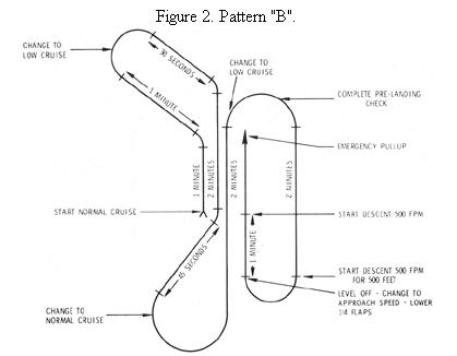 |
Lesson 17 - Radar Approach (PAR)
1. Brief Student Thoroughly Prior to Flight
2. Radar Pattern
a. Position the aircraft on a downwind leg and on interphone
simulate the initial call-up, the surveillance radar controller, and the
final controller.
b. The student reads back all headings and altitudes given, and
acknowledges all other transmissions except when instructed otherwise by
the final approach controller.
c. Perform the prelanding check on the downwind leg. Change airspeed
to initial approach airspeed and set flaps as appropriate.
d. Make all heading changes in the pattern with a standard rate
turn.
e. Turn to base leg and complete the final cockpit check.
f. Turn to the final approach heading, reduce airspeed to approach
speed, and make final flap setting. Maintain altitude and heading while
changing airspeed and setting flaps.
g. Enter a normal 500-foot per minute rate descent when so instructed
by the controller.
h. Final approach corrections:
(1) If above or below the glide path, make an approximate pitch
correction and monitor the airspeed indicator for the need of power change.
(2) When changing headings, do not exceed in bank angle the
number of degrees to be turned.
(3) Stress the importance of making immediate and precise corrections
when so instructed by the controller.
3. Student Practice
a. The instructor acts as the surveillance radar controller and
the final controller and has the student perform a simulated precision
radar approach at altitude.
b. Repeat the above to a landing runway. At simulated PAR minimums,
the instructor will take over and land the aircraft or have the student
perform a missed approach.