|
Chapter 3 — Components and Systems
Multiple Attachment Points Bracket
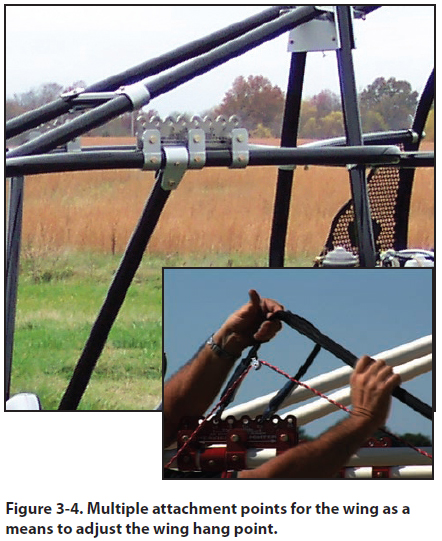
The attachment point bracket on the cart is one method
to select the fore and aft wing attachment position
for proper CG adjustments. [Figure 3-4] Always refer
to the POH for weight and balance information specific
to the powered parachute you are flying.

Center of Gravity Adjuster Tubes
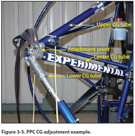
The term “CG tubes” sometimes refers to the three
tubes that meet at the point of rigging for the wing
(upper CG tube, lower CG tube and center CG tube).
[Figure 3-5] Sometimes the term “CG tube” refers
only to the tube that is adjustable, and the other tubes
that meet at the rigging points are called outrigger
arms.

Instrument Panel
The instrument panel is in front of the pilot and provides
engine and flight information. The pilot is responsible
for maintaining collision avoidance with
a proper and continuous scan surrounding the powered
parachute, as well as monitoring the information
available from the instrument panel. The pilot must
process the outside cues along with the instrumentation
throughout the flight for a sound decision-making
process.
The ignition switches are usually located on the instrument
panel and have two positions: ON, which
allows power to make contact with the spark plugs,
or OFF, which is a closed switch to GROUND and
removes the power source from the spark plugs. Typically,
PPC engines have two spark plugs per cylinder,
two switches and two completely separate ignition
systems. Some single place PPCs with smaller engines
have only a single spark plug per cylinder, one
ignition switch, and a single ignition system.
The FAA defines the required minimum instrumentation
for PPCs; engine manufacturers may recommend
certain instruments be installed on the aircraft
to monitor the performance of their particular engine.
For example, on a liquid-cooled engine, the manufacturer
may recommend instrumentation to monitor engine
gas temperatures (EGT), water temperatures and
RPM. On an air-cooled engine, the manufacturer’s
recommendation may be EGT, cylinder head temperature
(CHT) and RPM. Additional instruments can be
added as desired by the individual aircraft owner.
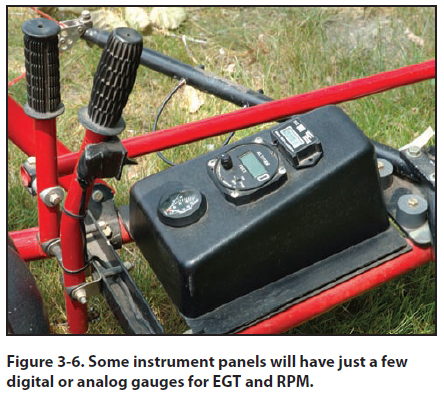
Some PPCs may only have a few analog gauges.
[Figure 3-6] Some makes and models may be
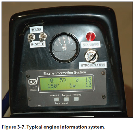
equipped with an engine information system (EIS).
[Figure 3-7] The EIS is a flight computer and screen
that receives input signals from sending units connected
to engine and flight probes or sensors. The computers
are pre-programmed for different makes and
models of engines. Engine information may include:
RPM, EGT, CHT, water temperature, fuel quantity, an
hour meter and a voltmeter. Flight instruments may
include altimeter, vertical speed indicator and a GPS.
 
This engine and flight information is viewed on the
LCD screen and has function keys, allowing the
pilot to move between display screens that contain the
computer’s input. When the display button is pressed, each individual screen will clearly identify the information
being displayed.
The information systems are also capable of alerting
the pilot when any engine or flight parameters are exceeded,
usually via a warning light mounted on the
instrument panel. Although the EIS is a valuable tool,
the ability to interpret the information is equally important.
For the interperetation of any engine and flight instrument,
you need to completely understand the engine
limitations, parameters, and the messages the instrument
provides you. Sensing the proper operation of the
aircraft and engine is a key factor to the safe operation
of any aircraft. Being able to interpret engine sounds
and unusual vibrations is essential for any pilot.
As with any aircraft or instrument operation, see the
POH for each individual make and model operating
instructions.
|

