|

This chapter covers the engines found on most powered
parachutes and includes the exhaust, ignition,
fuel, lubrication, cooling, propeller, gearbox, induction,
charging, and fuel systems. Reciprocating engine
operating theory is covered, for both two-stroke
and four-stroke engines.
The powered parachute engine and propeller, often
referred to as a powerplant, work in combination to
produce thrust. The powerplant propels the powered
parachute and charges the electrical system that supports
PPC operation.
The engine is one of the key components of a powered
parachute and should be maintained according to both
the engine and airframe manufacturer recommendations.
Preflight information, along with maintenance
schedules and procedures, can be found in the Pilot’s
Operating Handbook (POH) and/or maintenance references
from the manufacturers.
Engine inspections and maintenance must be performed
and documented in a logbook. You should
review this logbook before flying an unfamiliar powered
parachute.
Reciprocating Engines
Most powered parachutes are designed with reciprocating
engines. Two common means of classifying
reciprocating engines are:
1. By the number of piston strokes needed to
complete a cycle: two-stroke or four-stroke; and
2. By the method of cooling: liquid or air-cooled.
Refer to Chapter 5 of the Pilot’s Handbook of Aeronautical
Knowledge for a comprehensive review of
how reciprocating four-stroke engines operate.
Two-Stroke Engines
Two-stroke engines are commonly used in powered
parachutes. Two-stroke aviation engines evolved
from two-stroke snowmobile and watercraft engines, the difference being that an aircraft engine is optimized
for reliability with dual ignition often installed
for each cylinder. Two-stroke engines are popular because
they have fewer components than four-stroke
engines which makes them less expensive to manufacture,
and lighter, thus increasing their power-toweight
ratio.
Two-stroke engines require that oil be mixed into the
fuel to lubricate the engine, instead of being held in a
sump and having a separate recirculating system like
a four-stroke engine. Details on two-stroke oil mixing
are covered later under the “Lubrication” section.
One stroke as the piston moves up is intake and compression,
the second stroke as the piston moves down
is power and exhaust. The two-stroke engine performs
the same functions as a four-stroke engine in
half the strokes.
A wide range of valve systems are found on two
cycle engines, for the purpose of opening and closing
ports in the cylinder to let fuel in and exhaust out
at the proper time, similar to the intake and exhaust
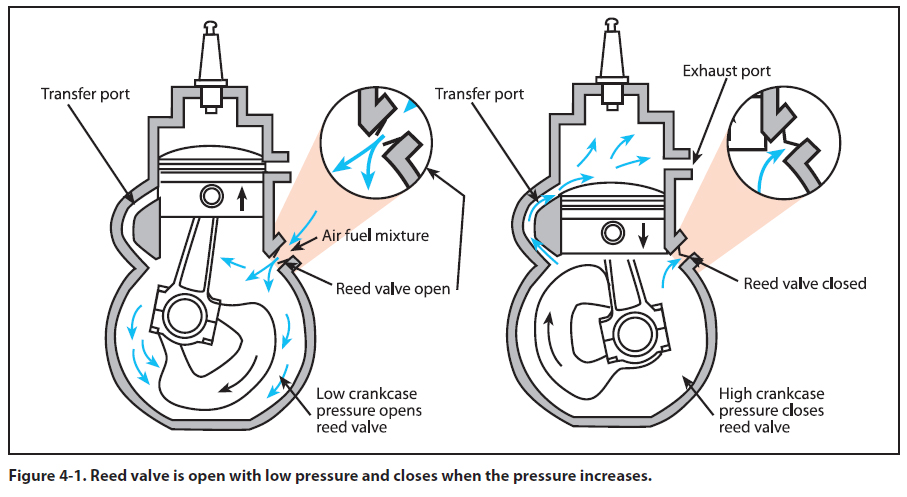
valves on a four-stroke engine. One-way pressure
valves, called spring, reed, or poppet valves, open
when the pressure drops within the crankcase, pulling
the fuel from the carburetor into the crankcase.
[Figure 4-1]
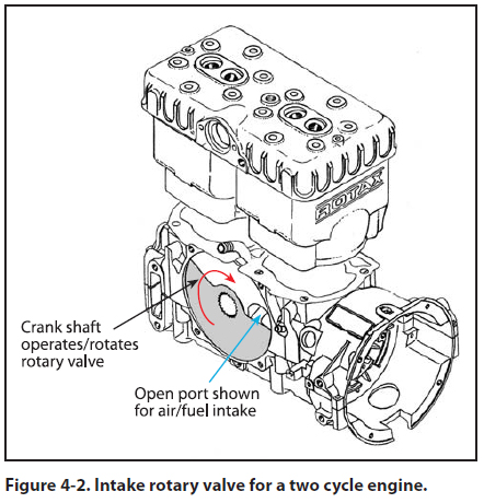
Mechanical rotary valves are driven off the engine,
rotate to provide an opening at the precise time, and
can be on the intake and exhaust ports. [Figure 4-2]
Piston porting does not use any valves. The fuel inlet
port is opened and closed by the piston position as
it moves up and down in the cylinder. This is called
a “piston ported inlet” and will be used in the Two-
Stroke Process description that follows. [Figure 4-3]
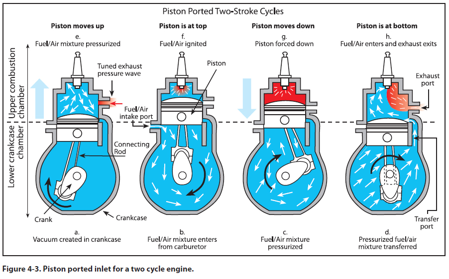
Two-Stroke Process
The two-stroke process begins with the fuel entering
the engine and concludes as it exits as exhaust.
[Figure 4-3]
Crankcase Vacuum Intake Stroke—Piston
Moving up: Figure 4-3 a to b
The upward stroke of the piston [Figure 4-3a] creates
a vacuum in the crankcase and pulls the fuel/
air/oil mixture into the crankcase through the intake
valve system from the carburetor. [Figure 4-3b] This
can be a pressure-actuated reed valve, a rotary valve,
or a third ported inlet system where the lower piston
skirt provides an opening for the fuel/air/oil mixture
to flow in when the piston is reaching its highest
point Top Dead Center (TDC). At this point, the
greatest portion of the fuel/air/oil mixture has filled
the crankcase.
Crankcase Compression Stroke—Piston
Moving down: Figure 4-3 b to c
During the downward stroke, the pressure valve is
forced closed by the increased crankcase pressure,
the mechanical rotary valve closes, or the piston
closes off the fuel/air oil mixture intake port. The
fuel mixture is then compressed in the crankcase
during the downward stroke of the piston.
Crankcase Transfer/Exhaust—Piston at lowest:
Figure 4-3 d
When the piston is near the bottom of its stroke, the
transfer port opening from the crankcase to the combustion
chamber is exposed, and the high pressure
fuel/air mixture in the crankcase transfers around the
piston into the main cylinder.
This fresh fuel/air/oil mixture pushes out the exhaust
(called scavenging) as the piston is at its lowest point and the exhaust port is open. Some of the fresh fuel/
air/oil mixture can escape out the exhaust port resulting
in the higher fuel use of the two stroke engine.
Cylinder start of Compression Stroke—Piston
initially Moving up: Figure 4-3 e
As the piston starts to move up, covering the transfer
port, the tuned exhaust bounces a pressure wave at
the precise time across the exhaust port (more on
this in the exhaust system discussion) to minimize the fuel/air/oil mixture from escaping out the exhaust
port.
Cylinder Compression Stroke—Piston Moving
Up: Figure 4-3 e to f
The piston then rises, and compresses the fuel mixture
in the combustion chamber. During this piston
compression process, the crankcase vacuum intake
process is happening simultaneously, as described
earlier. This is why four processes can happen in two
strokes.
Cylinder Power Stroke—Piston Moving Down:
Figure 4-3 f to g
At the top of the stroke, the spark plug ignites the
fuel mixture and drives the piston down as the power
stroke of the engine.
Cylinder Power Stroke—Piston Moving Down:
Figure 4-3 g to h
As the piston passes the exhaust port, the exhaust
starts to exit the combustion chamber. As the piston
continues down, the transfer port opens and the
swirling motion of the air/fuel/oil mixture pushes the
exhaust out the exhaust port.
Piston Reverses Direction From Down Stroke to
Up Stroke: Figure 4-3 h to a
As the piston reverses direction from the down
stroke to the up stroke the process is complete.
|

