Chapter 2
RIPCORD CABLE ROUTING
The routing of the ripcord cable from the handle to the
pin determines where the lanyard connects to the cable.
Most RSL attachments connect with the ripcord cable
either at the yoke area or just above the ripcord pin.
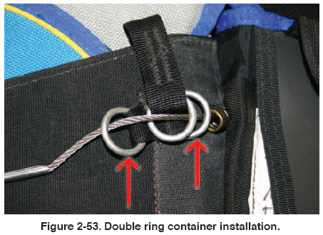
Generally, there is a double ring installation where the
cable end of the lanyard is located. [Figure 2-53] On this
particular installation, the connection is at the shoulder
yoke area.
RSL LANYARD AND CONTAINER MOUNT
These two components are interactive. That is, the design
of the container directly affects the design of the lanyard.
Once the two above locations are determined, then the
routing of the lanyard can be completed. It was originally
thought that the lanyard should have a long length to
allow acceleration during activation to pull the ripcord
cable. This has not proven to be true and most manufacturers
keep their lanyards as short as possible to prevent
snagging and easier stowing.
In the past, a Velcro® pathway was used for routing the
lanyard. This was either on the shoulder yoke or the
reserve riser. Experience has shown that the use of
Velcro® generally results in high wear and eventual damage
to the webbing. [Figure 2-54] On this design, the lanyard is stiffened with a short piece of coated cable and
stowed in two pockets located on the yoke area. [Figure
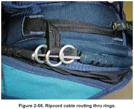
2-55] It is secure and has no wear points. The ripcord end
of the lanyard is routed to the dual guide ring attachment
location and the ripcord cable routed through the rings.
[Figure 2-56] The ripcord cable is then routed to the
reserve closing loop.
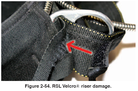 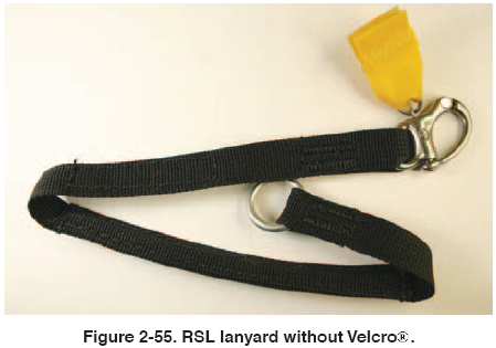
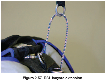
Figure 2-57 shows the RSL lanyard and ripcord cable at
the moment of riser extension and just as the cable is loaded. A point that the rigger should be aware of is the
“pigtail” configuration of the reserve ripcord that results
from the use of the RSL. [Figure 2-58] Because of the
sliding of the ring along the ripcord cable, a curling effect
is imparted to the cable. This is a clear indication that the
RSL lanyard activated the reserve. The rigger should
carefully inspect the ripcord cable for any broken strands.
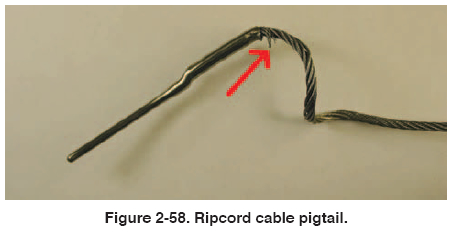
If any are found, the ripcord should be replaced. If not,
the cable can be straightened and returned to service.
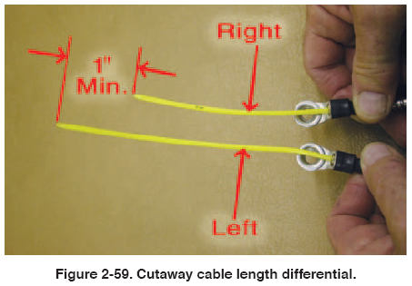
With the single side RSL, it is imperative that the main
riser with the RSL attachment leave after the opposite
riser. If the opposite riser stays connected while the
RSL deploys the reserve, there is the possibility of a
main/reserve entanglement. To ensure the correct staging of the cutaway, the release cable of the RSL side must be
longer than the cable on the opposite riser. A minimum of
1" is the standard differential. [Figure 2-59]
| 
