Chapter 2
CONTAINERS
The container component assembly of the parachute system
is that part which encloses the canopy(s) and lines,
the deployment device if used, and the pilot chute. It is
held closed by the use of cones or loops, which are
secured by ripcord pins or locking pins such as are used
on hand deploy systems. Containers may consist of single
units as are used on pilot emergency systems, or multiple
units such as are used on skydiving piggyback systems.
The term “pack” is used interchangeably with container.
The harness and container assembly may be called the
pack and harness. The term “packtray” is used to refer to
the bottom panel or section of the container where the
lines may be stowed during packing.
Early containers were simply a bag-shaped unit that the
canopy was stuffed into and then tied closed. The parachute
was static line deployed and the parachutist simply
fell away from the balloon or aircraft allowing the canopy
to deploy. With the advent of manually deployed free fall
systems, the need for a more secure and tailored design
became evident.
Originally, the parachute systems were identified by the
position at which they were located in relation to the body of the user. These were the back parachute, seat parachute,
chest parachute, and lap parachute. The containers
were usually rectangular in shape with four
closing flaps. These configurations were primarily dictated
by the need to fit the assembly into the cockpit of
the aircraft.
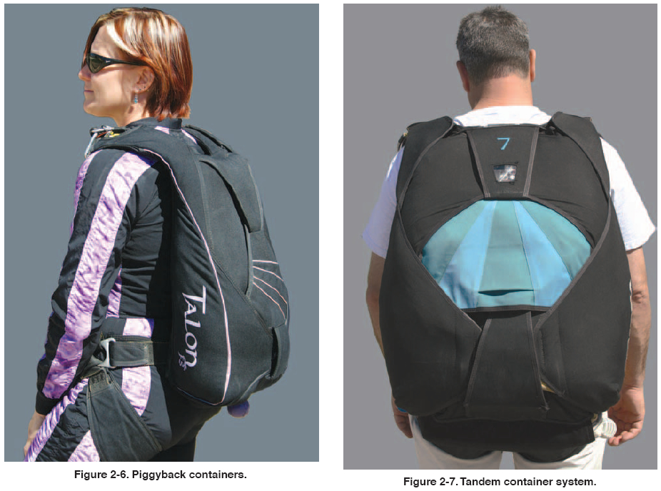
With the growth of skydiving, the container configurations
and the associated terminology changed. The original
location of the main parachute on the back and the
reserve on the chest became known as the “conventional”
configuration. [Figure 2-5] The original tandem configuration
with both the main and reserve on the back became
known as a “piggyback” [Figure 2-6], and the introduction
of a two-person parachute system became the new
“tandem.” [Figure 2-7]
CONFIGURATION
When canopies were packed into early bag-type containers,
they always wanted to assume a spherical or round
shape. For the container to remain flat, it was necessary to
tailor the fabric and then use frames or bow stiffeners to
keep it flat and compress the pilot chute. Back designs
utilized multiple cones and pins, usually three or four to
maintain the length and width. Seat containers were
usually more square and thicker since they were held in
place by the seat pan. Most use two cones and pins
for closing. The same was used for chest and lap parachutes. Many military systems still utilize these basic
configurations today.
With the introduction of skydiving in the 1960s, most
equipment was of modified military designs, and the first
generation of commercial products were simply colored
versions of these designs. In the 1970s, skydiving
canopies had progressed to ram-air designs, which were
smaller in volume and had different deployment requirements.
Container designs evolved to meet these requirements.
The introduction of the hand deploy pilot chute
was probably the most influential concept in the evolving
container design. Cones were replaced by fabric closing
loops, and main ripcords and pins were replaced by hand
deploy bridles and locking pins. It was no longer necessary
to compress the spring-loaded pilot chute inside the
container. Thru closing loops were used to compress the
pack and make it thinner to conform to the body shape.
The use of deployment bags and other devices helped
provide shaping to the container. This was true for both
square and round canopies.
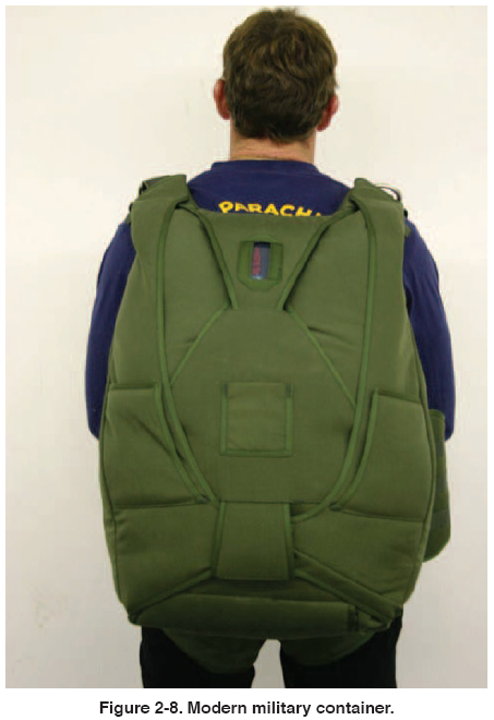
Today, most modern container designs have completely
done away with frames and bow stiffeners. This has
resulted in smaller, more flexible, more comfortable, and
more efficient container designs. Instead of metal stiffeners,
nylon plastic is used to reinforce the container flaps
for backing the grommets. The nylon is lighter, easier to
work with, and cheaper. Many of the modern military designs now follow the design concepts pioneered by the
sport industry as they have proven better and more cost
effective. Figure 2-8 shows the similarity to a sport piggyback
system.
| 
