Chapter 5
CANOPY ASSEMBLY AND LINE CONTINUITY
The first task is to check the line continuity of the canopy.
The following method may be used by riggers who do not
have access to a canopy hanger. Figure 5-22 shows examples
of a seven-cell and nine-cell canopy when viewed
from the bottom as by the jumper when in flight. The
examples show the line attachment nomenclature referred
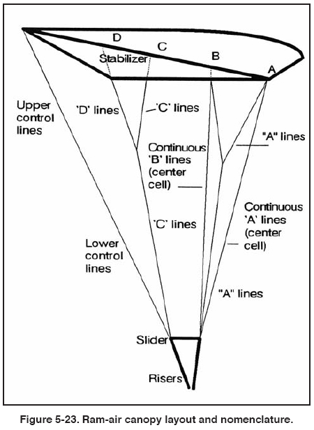
to in the continuity check. Figure 5-23 shows the standard
canopy nomenclature as referred to in the continuity
check.
1. First, lay out the canopy on its left side, the slider spanwise
with its tape down, and lay out the container with the
harness up.
2. If slider bumpers are used, thread one bumper over
each riser and down a few inches.
3. Place the slider on the risers spanwise, with its tape facing
the canopy.
4. Locate the leading edge and A line attachment. Follow
the line 8A (10A) to the outboard side of its link and
attach the link to the right riser, finger tight.
5. Pick up line 1A at the canopy attach point. Follow it
down to the outboard side of its link and attach the link to
the left front riser, finger tight.
6. Turn the container over, harness down, and orient the
rear risers to receive their respective links. This simplifies
C/D link attachment.
7. Rotate the leading edge under the rest of the canopy.
Split the aft section along with its associated control line
groups to make the C/D links easily accessible for routing
and installation.
8. Locate the data panel at the center cell’s upper surface
trailing edge. From this center reference point, follow the
trailing edge to the left stabilizer and pick up line 1D.
9. Route this line to the outboard side of its link and attach
the link to the left rear riser, finger tight.
10. Again from the center reference, follow the trailing
edge to the right stabilizer and pick up line 8D (10D).
11. Route this line to the outboard side of its link and
attach the link to the right rear riser, finger tight.
12. Return to the center reference point of the trailing
edge. Locate and pick up the left side upper control lines
consecutively. Verify their continuity to the junction with
the lower control line.
13. Removing twists as you go, follow the left lower control
line to its running end. Route it through the appropriate
slider grommet, and then through the guide ring.
14. Remove the toggle from the riser and route the running
end of the lower control line through the toggle
attachment loop or grommet.
15. Slide the toggle up to the mark on the control line.
Secure it with an overhand knot tied closely to the toggle.
16. The control line attachment for the right side is done
in a similar manner.
17. When the control line installation is complete, compare
the two toggle settings under equal tension to ensure
their uniformity.
18. At this time, verify the continuity of the control line
system. Begin at the trailing edge on each side, ensuring
that all twists have been removed from the upper and
lower control lines. Check that the lower control lines
have been properly routed through their appropriate slider
grommets and that the toggles have been properly secured
equidistant from the trailing edge.
19. Separate the aft section and control line groups to
their respective sides and locate the center reference point
at the trailing edge.
20. Following the trailing edge control surface outboard
will lead the rigger to the left stabilizer’s bottom seam
and the attachment point of line 1D.
21. Holding D lines 1,2,3, and 4 (1,2,3,4,5) in your right
hand and D lines 5,6,7, and 8(6,7,8,9,10) in your left
hand, verify the continuity of the C and D lines through
the cascades to their respective rear risers.
22. Gather in the control lines and flip the canopy over so
the leading edge faces up. Verify this orientation by locating
the attachment points of A lines 1 and 8(10).
23. In the same direction you flipped the canopy, rotate
the container system harness up.
24. Pick up the front riser groups, follow them to the
canopy, and separate.
25. Pick up A lines 8,7,6, and 5 (10, 9,8,7,6). If you have
continuous center cell lines, follow the bottom seam
down and pick up line 5B (6B). Verify continuity of the A
and B lines, through the cascades, to the right front riser.
26. Pick up A lines 1,2,3, and 4 (and 5). If you have continuous
center cell lines, follow the bottom seam down
and pick up line 4B (5B). Verify continuity through the
cascades to the left front riser. The continuity check is
now complete.
27. Tighten the connector links with an appropriate size
wrench. Do not over tighten! Inspect the links for any
marks or damage possibly done during the tightening
process. Mark the barrel of the connector links with a telltale
mark.
28. Move the slider upward from the risers onto the suspension
lines.
29. Move the slider bumpers upwards and into position
over the connector links. Hand tack the bumpers in place
according to the type used.
| 
