![]()
|
|
||
| CHAPTER 2 —Principles of Seaplanes
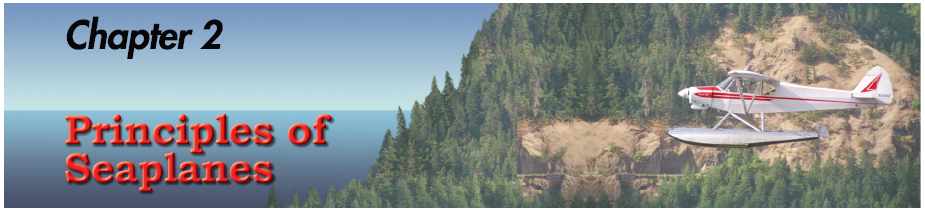
SEAPLANE CHARACTERISTICS There are two main types of seaplane: flying boats (often called hull seaplanes) and floatplanes. The bottom of a flying boat’s fuselage is its main landing gear. This is usually supplemented with smaller floats near the wingtips, called wing or tip floats. Some flying boats have sponsons, which are short, winglike projections from the sides of the hull near the waterline. Their purpose is to stabilize the hull from rolling motion when the flying boat is on the water, and they may also provide some aerodynamic lift in flight. Tip floats are sometimes known as sponsons. The hull of a flying boat holds the crew, passengers, and cargo; it has many features in common with the hull of a ship or boat. On the other hand, floatplanes typically are conventional landplanes that have been fitted with separate floats (sometimes called pontoons) in place of their wheels. The fuselage of a floatplane is supported well above the water’s surface. Some flying boats and floatplanes are equipped with retractable wheels for landing on dry land. These aircraft are called amphibians. On amphibious flying boats, the main wheels generally retract into the sides of the hull above the waterline. The main wheels for amphibious floats retract upward into the floats themselves, just behind the step. Additional training is suggested for anyone transitioning from straight floats to amphibious aircraft. [Figure 2-1]
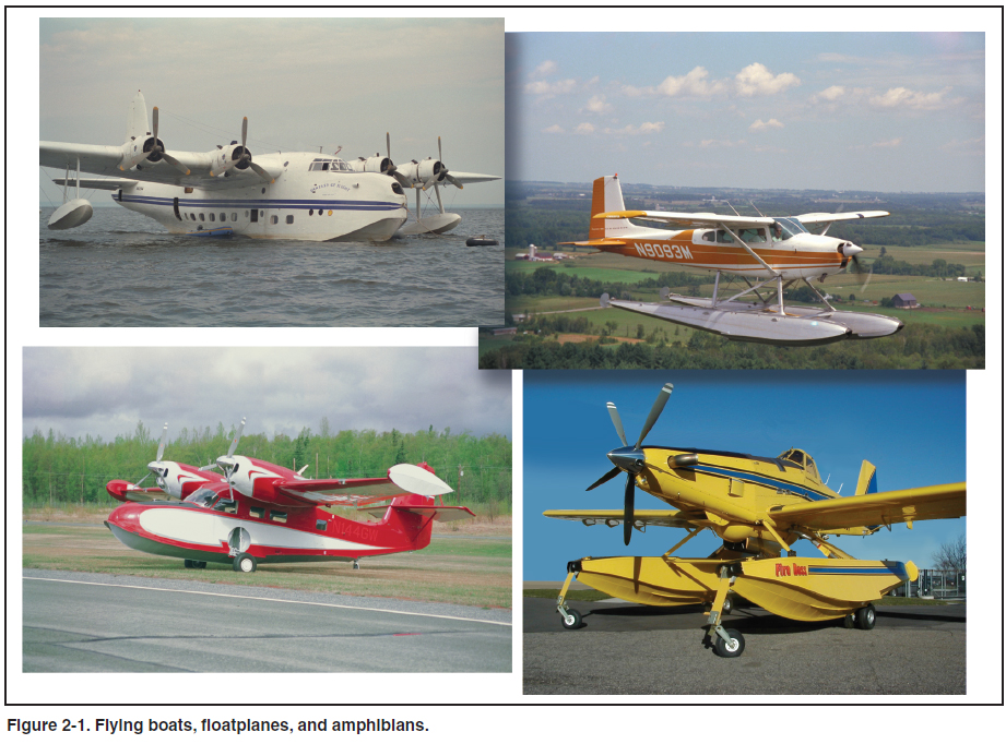
There are considerable differences between handling a floatplane and a flying boat on the water, but similar principles govern the procedures and techniques for both. This book primarily deals with floatplane operations, but with few exceptions, the explanations given here also apply to flying boats. A number of amphibious hull seaplanes have their engines mounted above the fuselage. These seaplanes have unique handling characteristics both on the water and in the air. Because the thrust line is well above the center of drag, these airplanes tend to nose down when power is applied and nose up as power is reduced. This response is the opposite of what pilots have come to expect in most other airplanes, and can lead to unexpected pitch changes and dangerous situations if the pilot is not thoroughly familiar with these characteristics. Pilots transitioning to a seaplane with this configuration should have additional training. Many of the terms that describe seaplane hulls and floats come directly from the nomenclature of boats and ships. Some of these terms may already be familiar, but they have specific meanings when applied to seaplanes. Figures 2-2 and 2-3 describe basic terms, and the glossary at the end of this book defines additional terms.
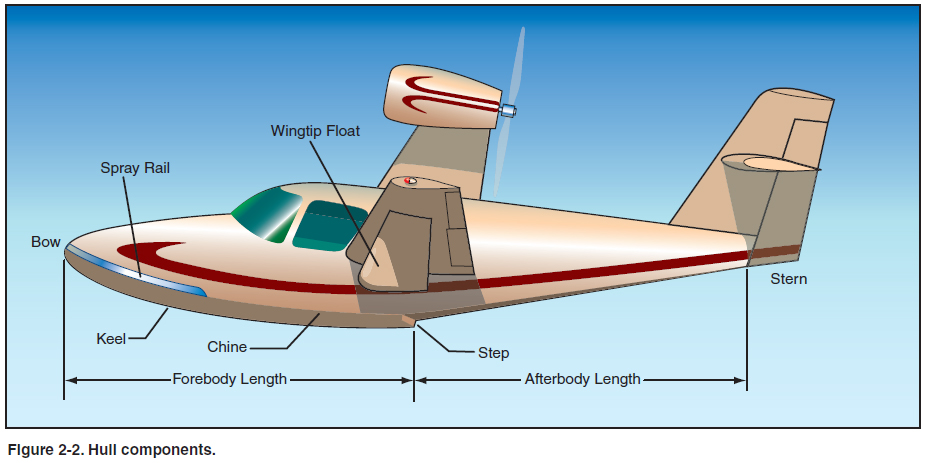
Other nautical terms are commonly used when operating seaplanes, such as port and starboard for left and right, windward and leeward for the upwind and downwind sides of objects, and bow and stern for the front and rear ends of objects. Research and experience have improved float and hull designs over the years. Construction and materials have changed, always favoring strength and light weight. Floats and hulls are carefully designed to optimize hydrodynamic and aerodynamic performance. Floats usually have bottoms, sides, and tops. A strong keel runs the length of the float along the center of the bottom. Besides supporting the seaplane on land, the keel serves the same purpose as the keel of a boat when the seaplane is in the water. It guides the float in a straight line through the water and resists sideways motion. A short, strong extension of the keel directly behind the step is called the skeg. The chine is the seam where the sides of the float are joined to the bottom. The chine helps guide water out and away from the float, reducing spray and helping with hydrodynamic lift. Hydrodynamic forces are those that result from motion in fluids. On the front portion of the float, midway between the keel and chine, are the two sister keelsons. These longitudinal members add strength to the structure and function as additional keels. The top of the float forms a deck that provides access for entering and leaving the cabin. Bilge pump openings, hand hole covers, and cleats for mooring the seaplane are typically located along the deck. The front of each float has a rubber bumper to cushion minor impacts with docks, etc. Many floats also have spray rails along the inboard forward portions of the chines. Since water spray is surprisingly destructive to propellers, especially at high r.p.m., these metal flanges are designed to reduce the amount of spray hitting the propeller. Floats are rated according to the amount of weight they can support, which is based on the weight of the actual volume of fresh water they displace. Fresh water is the standard because sea water is about 3 percent denser than fresh water and can therefore support more weight. If a particular float design displaces 2,500 pounds of fresh water when the float is pushed under the surface, the float can nominally support 2,500 pounds. A seaplane equipped with two such floats would seemingly be able to support an airplane weighing 5,000 pounds, but the floats would both be completely submerged at that weight. Obviously, such a situation would be impractical, so seaplanes are required to have a buoyancy of 80 percent in excess of that required to support the maximum weight of the seaplane in fresh water. To determine the maximum weight allowed for a seaplane equipped with two floats, divide the total displacement by 180 percent, or 1.8. Using the example of two floats that each displace 2,500 pounds, the total displacement of 5,000 pounds divided by 1.8 gives a maximum weight for the seaplane of 2,778 pounds. Many other considerations determine the suitability of a particular set of floats for a specific type of airplane, and float installations are carefully evaluated by the Federal Aviation Administration (FAA) prior to certification. All floats are required to have at least four watertight compartments. These prevent the entire float from filling with water if it is ruptured at any point. The floats can support the seaplane with any two compartments flooded, which makes the seaplane difficult to sink. Most floats have openings with watertight covers along the deck to provide access to the inside of each compartment for inspection and maintenance. There are also smaller holes connected by tubes to the lowest point in each compartment, called the bilge. These bilge pump openings are used for pumping out the bilge water that leaks into the float. The openings are typically closed with small rubber balls that push snugly into place. Both the lateral and longitudinal lines of a float or hull are designed to achieve a maximum lifting force by diverting the water and the air downward. The forward bottom portion of a float or hull is designed very much like the bottom of a speedboat. While speedboats are intended to travel at a fairly constant pitch angle, seaplanes need to be able to rotate in pitch to vary the wings’ angle of attack and increase lift for takeoffs and landings. The underside of a seaplane float has a sudden break in the longitudinal lines called the step. The step provides a means of reducing water drag during takeoff and during high-speed taxi. At very low speeds, the entire length of the floats supports the weight of the seaplane through buoyancy, that is, the floats displace a weight of water equal to the weight of the seaplane. As speed increases, aerodynamic lift begins to support a certain amount of the weight, and the rest is supported by hydrodynamic lift, the upward force produced by the motion of the floats through the water. Speed increases this hydrodynamic lift, but water drag increases more quickly. To minimize water drag while allowing hydrodynamic lift to do the work of supporting the seaplane on the water, the pilot relaxes elevator back pressure, allowing the seaplane to assume a pitch attitude that brings the aft portions of the floats out of the water. The step makes this possible. When running on the step, a relatively small portion of the float ahead of the step supports the seaplane. Without a step, the flow of water aft along the float would tend to remain attached all the way to the rear of the float, creating unnecessary drag. The steps are located slightly behind the airplane’s center of gravity (CG), approximately at the point where the main wheels are located on a landplane with tricycle gear. If the steps were located too far aft or forward of this point, it would be difficult, if not impossible, to rotate the airplane into a nose-up attitude prior to lifting off. Although steps are necessary, the sharp break along the underside of the float or hull concentrates structural stress into this area, and the disruption in airflow produces considerable drag in flight. The keel under the front portion of each float is intended to bear the weight of the seaplane when it is on dry land. The location of the step near the CG would make it very easy to tip the seaplane back onto the rear of the floats, which are not designed for such loads. The skeg is located behind the step and acts as a sort of chock when the seaplane is on land, making it more difficult to tip the seaplane backward. Most floatplanes are equipped with retractable water rudders at the rear tip of each float. The water rudders are connected by cables and springs to the rudder pedals in the cockpit. While they are very useful in maneuvering on the water surface, they are quite susceptible to damage. The water rudders should be retracted whenever the seaplane is in shallow water or where they might hit objects under the water surface. They are also retracted during takeoff and landing, when dynamic water forces could cause damage. |
| ©AvStop Online Magazine Contact Us Return To Books |