![]()
|
|
||
| CHAPTER 10. Airport Traffi c Patterns
Airport Operations Airports vary in complexity from small grass or sod strips to major terminals having multiple paved runways and taxiways. Regardless of the type of airport, the pilot must know and abide by the rules and general operating procedures applicable to the airport being used. These rules and procedures are based not only on logic or common sense but also on courtesy, and their objective is to keep air traffi c moving with maximum safety and effi ciency. The use of any traffi c pattern, service, or procedure does not alter the responsibility of pilots to see and avoid other aircraft. Generally, there are two types of airport operations:
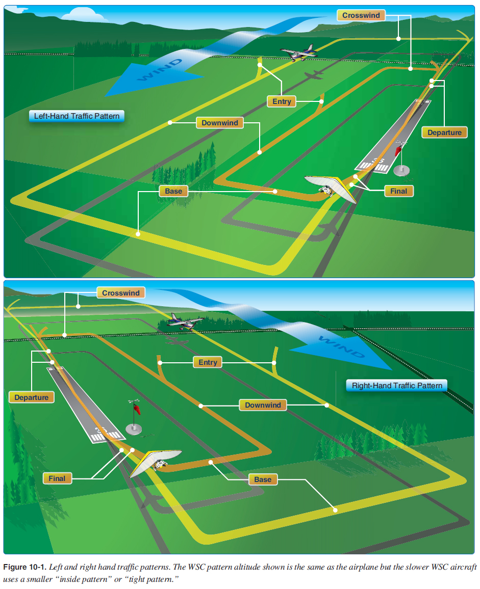
Airport operations is a prerequisite for reading and understanding this chapter. The Pilot’s Handbook of Aeronautical Knowledge (FAA-H-8083-25) chapter on airport operations is the starting point for this subject. Additionally, the portions of the Aeronautical Information Manual (AIM) covering aeronautical lighting and other airport visual aids, airspace, and air traffi c control, should be studied prior to reading this chapter. The following airport patterns are applicable to both towered and nontowered airport operations; however, in nontowered airports the pilot should use the information presented in this chapter along with the references provided in the summary to coordinate with the other air traffi c. When fl ying at towered airports, the principles must be understood to understand the air traffi c controller’s instructions. The pilot is always responsible for “see and avoid” and must continually look for other aircraft in towered and nontowered operations. Standard Airport Traffi c Patterns To assure that air traffi c fl ows into and out of an airport in an orderly manner, an airport traffi c pattern is established appropriate to the local conditions, including the direction and placement of the pattern, altitude to be fl own, and procedures for entering and leaving the pattern. Unless the airport displays approved visual markings indicating that turns should be made to the right, pilots should make all turns in the pattern to the left. When operating at an airport with an operating control tower, the pilot receives by radio a clearance to approach or depart, as well as pertinent information about the traffi c pattern. If there is not a control tower, it is the pilot’s responsibility to determine the direction of the traffi c pattern, to comply with the appropriate traffi c rules, and to display common courtesy toward other pilots operating in the area. The pilot is not expected to have extensive knowledge of all traffi c patterns at all airports; but if the pilot is familiar with the basic rectangular pattern, it is easy to make proper approaches and departures from most airports, regardless of whether they have control towers. At airports with operating control towers, the tower operator may instruct pilots to enter the traffi c pattern at any point or to make a straightin approach without fl ying the usual rectangular pattern. Many other deviations are possible if the tower operator and the pilot work together in an effort to keep traffi c moving smoothly. Jets or heavy aircraft frequently fl y wider and/or higher patterns than lighter aircraft and in many cases make a straight-in approach for landing. The standard rectangular traffic pattern and terms are illustrated in Figure 10-1. The terms of an airport in the pattern after takeoff are described in Figure 10-1.
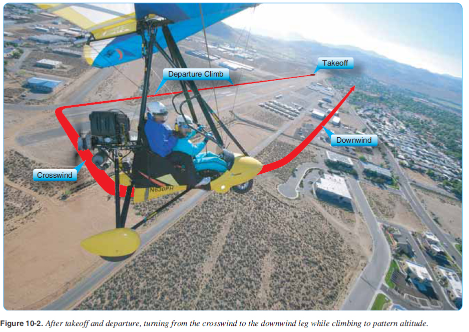
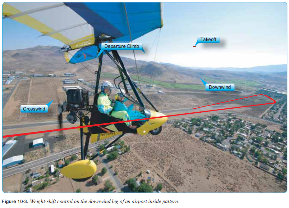
Departure leg—the fl ightpath which begins after takeoff and continues straight ahead along the extended runway centerline. Crosswind leg—a fl ightpath at right angles to the landing runway off its takeoff end. Downwind leg—a fl ightpath parallel to the landing runway in the opposite direction of landing. Base leg—a fl ightpath at right angles to the landing runway off its approach end and extending from the downwind leg to the intersection of the extended runway centerline (third left hand 90° turn). Final approach—a fl ightpath in the direction of landing along the extended runway centerline from the base leg to the runway. Upwind leg—a fl ightpath parallel to the landing runway in the direction of landing (not shown in Figure 10-1). The traffi c pattern altitude is usually 1,000 feet above the elevation of the airport surface; however, many airports use different pattern altitudes for different types of aircraft. This information can be found in the Airport/Facility Directory (A/FD). The use of a common or known altitude at a given airport is a key factor in minimizing the risk of collisions at airports without operating control towers because aircraft can be expected to be at a certain level making it easier to see. Compliance with the basic rectangular traffi c pattern reduces the possibility of confl icts at airports without an operating control tower. It is imperative that the pilot form the habit of exercising constant vigilance in the vicinity of airports even though the air traffi c appears to be light. The objective is to have both the fast and the slower weight-shift control (WSC) aircraft completing the pattern at the same interval. The slower the aircraft is, the tighter the pattern is, as shown in Figure 10-1. The terminology is a “tight pattern” or “inside pattern” for the slower WSC aircraft in operations with faster aircraft. Using Figure 10-1 as an example, if the airplane is fl ying the pattern at 80 knots and the WSC aircraft is fl ying an inside pattern at 40 knots (that is half the distance), then the WSC aircraft and the airplane will fl y around the pattern with the same interval. The WSC pilot must determine the size of the pattern to create the same interval. This is commonplace at nontowered airports where WSC aircraft operate with faster aircraft. Both aircraft are going around the pattern at the same time with the slower WSC aircraft fl ying a tighter pattern and the faster airplane fl ying the larger pattern. In Figure 10-2, the WSC aircraft is establishing an inside airport pattern turning from crosswind to downwind. In Figure 10-3, the aircraft shown is in the middle of the downwind leg fl ying an inside pattern.
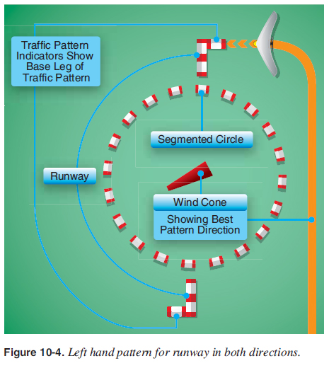
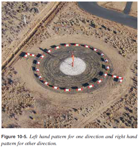
When entering the traffi c pattern at an airport without an operating control tower, inbound pilots are expected to listen to the other aircraft on the CTAF (Common Traffi c Advisory Frequency), observe other aircraft already in the pattern, and conform to the traffi c pattern in use. If other aircraft are not in the pattern, then traffi c indicators on the ground and wind indicators must be checked to determine which runway and traffi c pattern direction should be used. [Figure 10-4 and 10-5] Many airports have L-shaped traffi c pattern indicators displayed with a segmented circle adjacent to the runway. The short member of the L shows the direction in which traffi c pattern turns should be made when using the runway parallel to the long member. These indicators should be checked while at a distance away from any pattern that might be in use, or while at a safe height above pattern altitudes. When the proper traffi c pattern direction has been determined, the pilot should then proceed to a point clear of the pattern before descending to the pattern altitude.
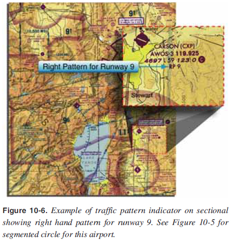
As discussed earlier, all patterns are left hand unless indicated otherwise. Sectional aeronautical charts list a right hand pattern along with the airport information as shown in Figure 10-6. The segmented circle of Figure 10-5 and the airport shown in Figure 10-6 both clearly show the patterns for this airport.
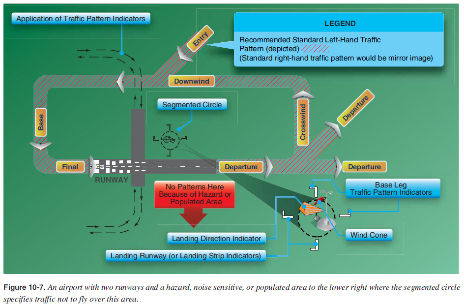
A segmented circle in Figure 10-7 provides traffi c patterns so there is no air traffi c over the lower right hand area, which could be a hazard or populated area.
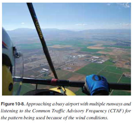
Inbound to an uncontrolled airport, the CTAF frequency should be monitored to listen for other aircraft in the pattern to fi nd out what is the active runway being used by other air traffi c. [Figure 10-8]
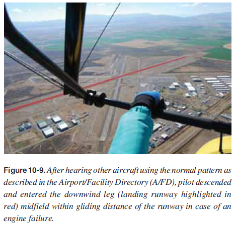
When approaching an airport for landing, the traffi c pattern should be entered at a 45° angle to the downwind leg, headed toward a point abeam of the midpoint of the runway to be used for landing as shown in Figures 10-1 and 10-7. Arriving aircraft should be at the proper traffi c pattern altitude before entering the pattern and should stay clear of the traffi c fl ow until established on the entry leg. Entries into traffi c patterns while descending create specifi c collision hazards and should always be avoided. During the WSC 45° entry into the pattern, the WSC aircraft must pass through the larger airplane pattern, so it is essential that alert see-andavoid procedures plus additional radio communications be practiced during this transition. The entry leg should be of suffi cient length to provide a clear view of the entire traffi c pattern and to allow the pilot adequate time for planning the intended path in the pattern and the landing approach. The downwind leg is a course fl own parallel to the landing runway but in a direction opposite to the intended landing direction. This leg for the slower WSC aircraft should be approximately ¼ to ½ mile out from the landing runway, and at the specifi ed traffi c pattern altitude unless the airport specifi cally specifi es a lower altitude for WSC aircraft. [Figure 10-9] The faster airplanes would be ½ to 1 mile out from the landing runway. During this leg, the before landing check should be completed. Pattern altitude should be maintained until abeam the approach end of the landing runway. At this point, power should be reduced and a descent begun. The downwind leg continues past a point abeam the approach end of the runway to a point approximately 45° from the approach end of the runway, and a medium bank turn is made onto the base leg.
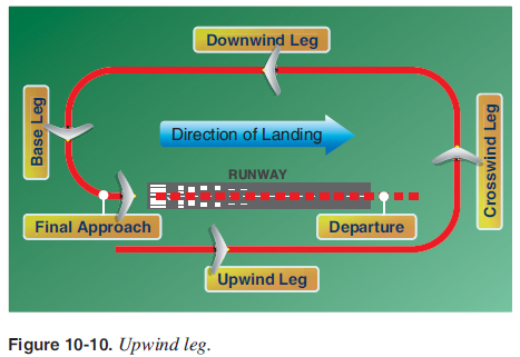
The base leg is the transitional part of the traffi c pattern between the downwind leg and the final approach leg. Depending on the wind condition, it is established at a suffi cient distance from the approach end of the landing runway to permit a gradual descent to the intended touchdown point. The ground track of the aircraft while on the base leg should be perpendicular to the extended centerline of the landing runway, although the longitudinal axis of the aircraft may not be aligned with the ground track when it is necessary to turn into the wind to counteract drift. While on the base leg and before turning onto the fi nal approach, the pilot must ensure that there is no danger of colliding with another aircraft that may be on the fi nal approach. This is especially important since the WSC aircraft is in a tighter pattern and could be fl ying onto the fi nal approach of faster airplanes. The fi nal approach leg is a descending fl ightpath starting from the completion of the base-to-fi nal turn and extending to the point of touchdown. This is probably the most important leg of the entire pattern because the pilot’s judgment and procedures must be the sharpest to control the airspeed and descent angle accurately while approaching the intended touchdown point. As stipulated in 14 CFR part 91, aircraft while on fi nal approach to land or while landing have the right-of-way over other aircraft in fl ight or operating on the surface. When two or more aircraft are approaching an airport for the purpose of landing, the aircraft at the lower altitude has the right of way. A pilot should not take advantage of this rule to cut in front of or overtake another aircraft on fi nal approach. The departure leg of the rectangular pattern is a straight course aligned with, and leading from, the takeoff runway. This leg begins at the point the aircraft leaves the ground and continues until the 90° turn onto the crosswind leg is started. On the departure leg after takeoff, the pilot should continue climbing straight ahead, and, if remaining in the traffi c pattern, commence a turn to the crosswind leg beyond the departure end of the runway within 300 feet of pattern altitude. If departing the traffi c pattern, continue straight out or exit with a 45° turn (to the left when in a left-hand traffi c pattern; to the right when in a right-hand traffi c pattern) beyond the departure end of the runway after reaching pattern altitude. An upwind leg is a course fl own parallel to the landing runway, but in the same direction as the intended landing direction. The upwind leg continues past a point abeam the departure end of the runway to where a medium bank 90° turn is made onto the crosswind leg. The upwind leg is also the transitional part of the traffi c pattern when on the fi nal approach and a go-around is initiated and climb attitude is established. When a safe altitude is attained, the pilot should commence a shallow bank turn to the right side of the runway. This allows better visibility of the runway for departing aircraft. [Figure 10-10]
The crosswind leg is the part of the rectangular pattern that is horizontally perpendicular to the extended centerline of the takeoff runway and is entered by making approximately a 90° turn from the departure or upwind leg. On the crosswind leg, the aircraft proceeds to the downwind leg position. In most cases, the takeoff is made into the wind in which case it is now approximately perpendicular to the aircraft’s fl ightpath. As a result, the aircraft has to be turned or headed slightly into the wind while on the crosswind leg to maintain a ground track that is perpendicular to the runway centerline extension. |
| ©AvStop Online Magazine Contact Us Return To Books |