![]()
|
|
||
| CHAPTER 11. Approaches and Landings
Normal (Calm Wind) Approaches and Landings A normal or regular approach and landing involves the use of procedures for what is considered a simple situation. It provides the minimum number of variables for the student pilot to learn during the fi rst landings; that is, when engine power is at idle, wind is light, and the fi nal approach is made directly into the wind, the fi nal approach path has no obstacles, and the landing surface is fi rm and of ample length to bring the aircraft gradually to a stop. This includes normal runways used for WSC that are asphalt, concrete, solid dirt, gravel or short grass. The selected landing point should be beyond the runway’s approach threshold but within the fi rst one-third portion of the runway. The factors involved and the procedures described for the normal approach and landing also have applications to the other-than-normal approaches and landings which are discussed later in this chapter. Therefore, the principles of simple (or normal) operations are explained fi rst and must be understood before proceeding to more complex operations. To assist the pilot in understanding the factors that infl uence judgment and procedures, the last part of the approach pattern and the actual landing is divided into fi ve phases:
Remember that the manufacturer’s recommended procedures, including aircraft confi guration, airspeeds, power, and other information relevant to approaches and landings in a specifi c make and model aircraft are contained in the Aircraft Flight Manual (AFM) and/or Pilot’s Operating Handbook (POH) for that aircraft. If any of the information in this chapter differs from the aircraft manufacturer’s recommendations as contained in the AFM/POH, the aircraft manufacturer’s recommendations take precedence. Throttle Use As discussed in Chapter 2, Aerodynamics, the WSC aircraft has a good glide ratio, and normal landings can easily be done with the power at idle. It is a good practice to master the landings with the throttle at idle so that the glide angle, speeds, and descent rates become habit and part of a normal routine. This is helpful so that, if there is an engine failure, the pilot is accustomed to landing with minimum power and is able to spot land the WSC aircraft for emergency conditions at or beyond a specifi ed point. As a general practice for normal landings in calm conditions or a slight headwind, the throttle should be brought back to idle at the start of the base leg for landings. Title 14 of the Code of Federal Regulations (14 CFR), section 91.119, Minimum Safe Altitudes: General, is an important safety precaution and states: “Except when necessary for takeoff or landing, no person may operate an aircraft anywhere below... an altitude allowing, if a power unit fails, an emergency landing without undue hazard to persons or property on the surface.” This allows long fi nal approaches “with power when necessary,” but overall, it is important to be no lower than an altitude from which you can glide to a safe landing area. For the purposes of this approach-and-landing discussion, it is assumed that there are no safe landing areas other than the runway. It should be noted that the power is above idle for some landing situations, such as:
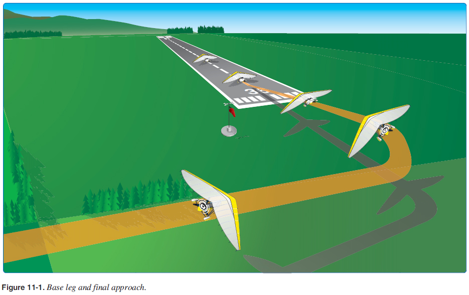
For landings where throttle is required, the foot throttle is typically used so the hands can stay on the control bar while approaching the ground for this critical phase of fl ight. However, the hand/cruise throttle may be set above idle for specifi c situations as required by the pilot. Higher power settings for approaches and landings are discussed later in this chapter. Base Leg The placement of the base leg is one of the more important judgments made by the pilot in any landing approach. [Figure 11-1] The pilot must accurately judge the altitude and distance from which the descent results in landing at the desired point.
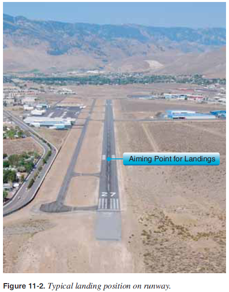
The base leg should be started at a point where the power can be brought back to idle and the WSC aircraft can glide to the landing spot at the approach speed recommended by the manufacturer. The intended landing point should not be at the end of the runway on a threshold or numbers, but beyond at the landing lines. [Figure 11-2] This provides some margin if the landing is shorter than anticipated. For smaller runways that do not have these markings, establish an appropriate landing point beyond the start of the runway, allowing plenty of room for the after-landing roll. At much larger airports, the landing can be done farther down the runway or at a location where the pilot can taxi off the runway and not delay other air traffi c behind the aircraft.
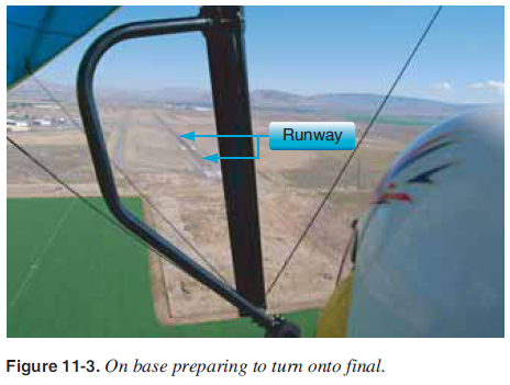
After turning onto the base leg, the pilot should continue the descent with reduced power and approach airspeed as recommended by the manufacturer. As discussed in Chapter 7, Takeoff and Departure, this speed is at least 1.3 times the stall speed. Landing trim should be adjusted according to manufacturer specifi cations (if equipped). Drift correction should be established and maintained to follow a ground track perpendicular to the extension of the centerline of the runway on which the landing is to be made. Since the fi nal approach and landing are normally made into the wind, there may be a crosswind during the base leg. The aircraft must be angled suffi ciently into the wind to prevent drifting farther away from the intended landing point. The base leg should be continued to the point where a medium- to shallow-banked turn aligns the aircraft’s path directly with the centerline of the landing runway. This descending turn should be completed at a safe altitude that is dependent upon the height of the terrain and any obstructions along the ground track. The turn to the fi nal approach should also be suffi ciently above the airport elevation to permit a fi nal approach long enough for the pilot to accurately estimate the resultant point of touchdown, while maintaining the proper approach airspeed. This requires careful planning for the starting point and radius of the turn. [Figure 11-3] Normally, it is recommended that the angle of bank not exceed a medium bank because the steeper the angle of bank, the higher the airspeed at which the aircraft stalls. Since the base-to-fi nal turn is made at a relatively low altitude, it is important that a stall not occur at this point. If an extremely steep bank is needed to prevent overshooting the proper fi nal approach path, it is advisable to discontinue the approach, go around, and plan to start the turn earlier on the next approach rather than risk a hazardous situation.
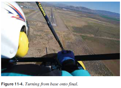
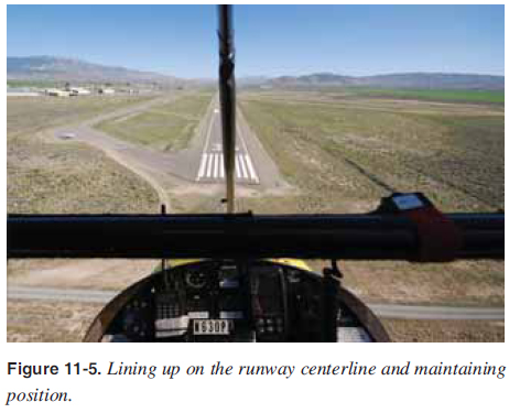
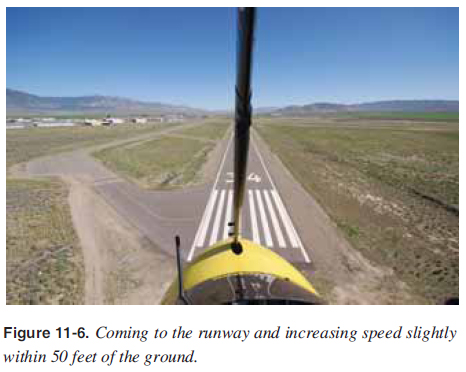
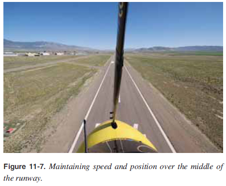
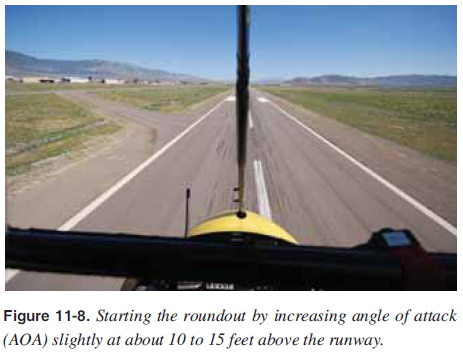
Final Approach After the base-to-final approach turn is completed, the aircraft should be aligned directly in the extension of the centerline of the runway. The objective of a good fi nal approach is to approach the runway with suffi cient energy (manufacturer’s recommended airspeed) to land at or beyond some predetermined point. The landing area should provide suffi cient runway behind for variations in approach conditions and runway ahead to allow either a full stop or a go-around if needed. If there is a crosswind of any kind, the aircraft should be pointed into the wind slightly (see the Crosswind Approaches and Landings section). Focus should be to keep the ground track aligned with the centerline of the runway or landing surface, so that drift (if any) is recognized immediately. On a normal approach, with no crosswind drift, the longitudinal axis should be kept aligned with the runway centerline throughout the approach and landing. After aligning the aircraft with the runway centerline, speed is adjusted as required for the desired rate of descent. Slight increases in power, if lower than expected, may be necessary to maintain the descent angle at the desired approach airspeed. The descent angle should be controlled throughout the approach so that the aircraft lands in the center of the runway at the aiming point, as discussed earlier. The descent angle is affected by all four fundamental forces that act on an aircraft (lift, drag, thrust, and weight). If all the forces are constant, the descent angle is constant in calm air. The pilot can control these forces by adjusting the airspeed and power. The fi nal approach sequence is shown in Figures 11-4 through 11-8.
In a descent for fi nal approach, if the WSC is slowed with an angle of attack that is too high and without an increase of power, the aircraft settles very rapidly and touches down short of the desired area. For this reason, the pilot should never try to stretch a glide by applying forward control bar pressure alone to reach the desired landing area. Because this brings the speed below the minimum drag speed, the gliding distance decreases if power is not added simultaneously. Additionally, this is a lower energy approach and may be slower than the manufacturer’s safe approach speed. The proper angle of descent to the runway must be maintained at the minimum speed recommended by the manufacturer, with a fl atter descent angle obtained with increases in power as required. Steeper descent angles are obtained with headwinds or the pilot increasing speed/decreasing the angle of attack, both of which are covered later in this chapter. |
| ©AvStop Online Magazine Contact Us Return To Books |