![]()
|
|
||
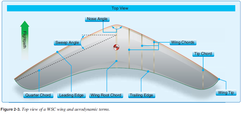
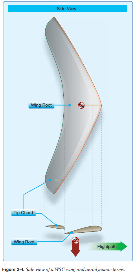
CHAPTER 2. Aerodynamics 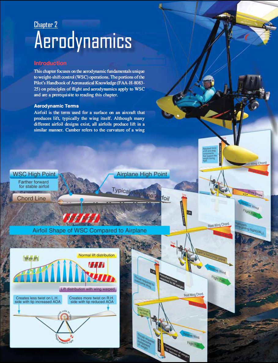 when looking at a cross-section. A wing possesses upper camber on its top surface and lower camber on its bottom surface. WSC airfoils can be single surface, with one piece of fabric for most of the airfoil, for slower wings. Faster airfoils have two surfaces and are called double surface wings, which are more like an airplane wing. [Figure 2-1] This double surface allows the wing structure to be enclosed inside the wing, similar to an airplane wing, reducing drag and allowing for faster speeds for the same thrust. The leading edge is the forward edge of the airfoil, and the rear edge of the airfoil is called the trailing edge. The chord line is an imaginary straight line drawn from the leading edge to the trailing edge. The WSC airfoil typically uses a different camber with the airfoil high point farther forward than the airplane airfoil, creating a more stable airfoil. [Figure 2-2] 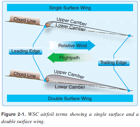 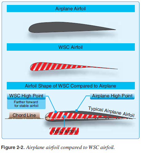 The WSC wing is a unique design of airfoils that differ throughout the wing span. Looking at a top view of the wing, in the center is the wing root and on each end is the wingtip. Wing chord is any section of the wing parallel to the wing root. [Figures 2-3 and 2-4] The wingtip chord is the chord where the trailing edge is furthest to the rear of the wing. This can be inboard of the tip (as shown) and can vary depending on the specifi c wing design. The nose angle is the angle made by the leading edges, typically ranging from 120° to 130°. Sweep is the angle measured between the quarter chord line (line of 25 percent chords) and a line perpendicular to the root chord. [Figure 2-3]
Looking at the rear view of the wing, anhedral is the angle the wings make angling down and dihedral is the angle the wings make angling up. [Figure 2-5] Dihedral is the positive angle formed between the lateral axis of an airplane and a line which passes through the center of the wing. Anhedral is the similar negative angle. Wings with sweep have an “effective dihedral” characteristic that counteracts the physical anhedral to develop the required roll stability for the particular make/ model design objective. This is explained in the Pilot’s Handbook of Aeronautical Knowledge in much greater detail for further reference. Unlike airplanes which typically have signifi cant dihedral as viewed from the front or back for roll stability, WSC wings typically have a slight amount of anhedral as shown in Figure 2-5 and effective dihedral which is a characteristic of the swept wing design. 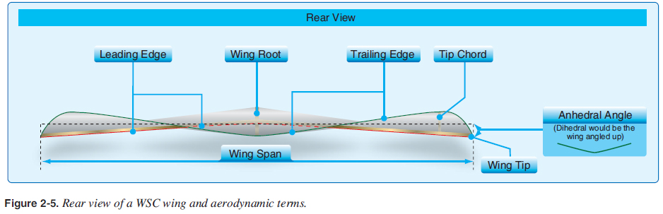 Wing twist is the decrease in chord angle from the root to the tip chord, common to all WSC wings and ranging from 5° to 15°. This wing twist is also called washout as the wing decreases its angle of attack from root to tip. The term billow was originally used for the early Rogallo wings as the additional material in degrees that was added to the airframe to create the airfoil. It is still used today to defi ne the amount of twist or washout in the wing. The WSC may not have twist/washout when sitting on the ground, and must be fl ying and developing lift to display the proper aerodynamic twist characteristic of WSC wings. [Figure 2-6] 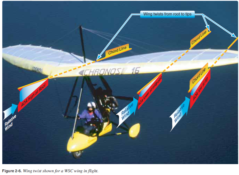 The longitudinal axis is an imaginary line about which the aircraft rolls around its center of gravity (CG); it is also called the roll axis. The longitudinal axis is not necessarily a fi xed line through the carriage because the roll axis changes for different fl ight confi gurations, but can be approximated by the middle of the propeller shaft for a properly designed WSC aircraft and is typically parallel with the fl ightpath of the aircraft as shown in Figure 2-7. Angle of incidence is the angle formed by the root chord line of the wing and the longitudinal axis of the WSC aircraft. 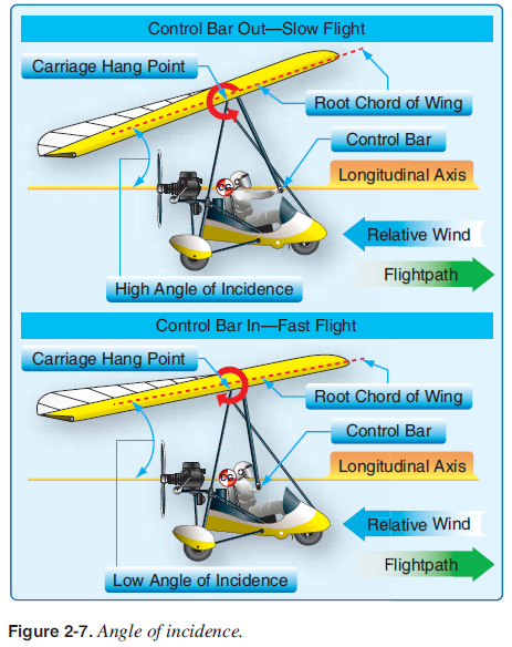 Unlike that of an airplane, the WSC angle of incidence has a signifi cant change in fl ight because the carriage is attached to the wing, which allows the wing to rotate around the carriage hang point on the wing and is controlled by the pilot as shown in Figure 2-7. Pitch angle is the angle the WSC wing root chord (center of wing) makes with the Earth’s horizontal plane. Many pilots confuse the pitch angle, which is easily seen and felt, with the angle of attack (AOA) which is not as perceptible. For example, if fl ying in a glide with the engine idle and the nose lowered, the pitch angle can be below the horizon. Another example would be fl ying at full power climb with the nose raised, resulting in the pitch angle being well above the horizon. [Figure 2-8] Pitch angles are covered in greater detail in chapter 6. 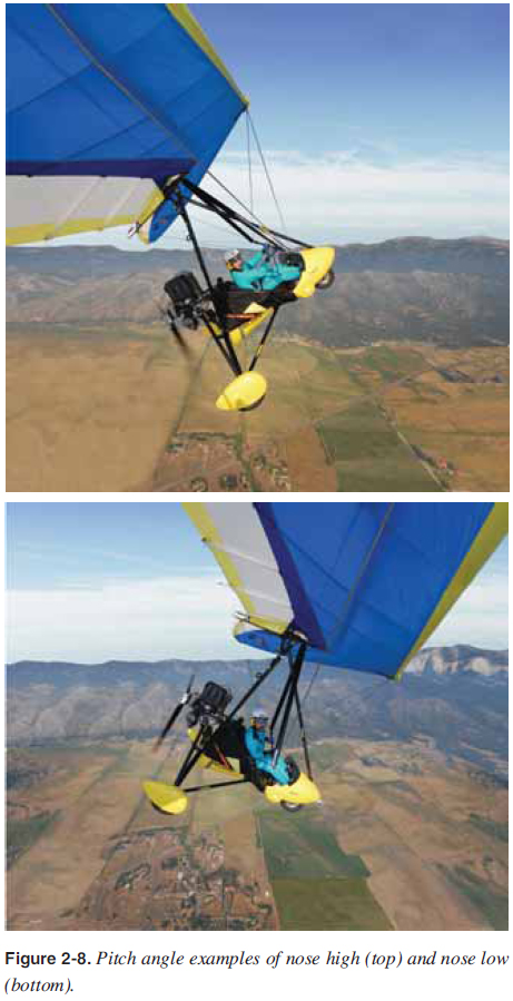 Deck angle is the angle of the cart’s wheel axles to the landing surfaces, as in the powered parachute (PPC) deck angle. Relative wind is the direction of the airfl ow with respect to the wing; it is parallel to and opposite the WSC fl ightpath. Relative wind may be affected by movement of the WSC through the air, as well as by all forms of unstable, disturbed air such as wind shear, thermals, and turbulence. When a WSC is fl ying through undisturbed air, the relative wind is parallel to and opposite the fl ightpath. [Figure 2-7] AOA is the angle between the relative wind and the wing chord line. Because of the wing twist, the AOA is greatest at the wing root and decreases along the wing span to the tips. This is an important concept covered in the stability section of this chapter. For changing speeds during gliding, level fl ight, and climbs, AOA is the primary control for speed changes. Lower angles of attack produce higher speeds, and higher angles of attack result in slower speeds. The pilot changes the AOA by moving the control bar forward for high angles of attack and slow speeds as shown in Figure 2-7 (top) for high angle of incidence and Figure 2-8 (top) for high pitch angle. Low angles of attack for fast speeds are shown in Figure 2-7 (bottom) for low angle of incidence and Figure 2-8 (bottom) for low pitch angle. Most of the time, the pilot is fl ying at the cruise AOA, which is the trim position of the control bar, and the pilot is neither pushing out nor pulling in on the control bar. This trim position is the AOA and speed the aircraft fl ies if the pilot is fl ying straight and releases the control bar in calm air. [Figure 2-9, middle] 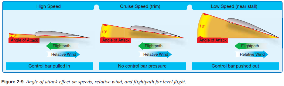 Planform is the shape or form of a wing as viewed from above. The WSC wing comes in a number of planforms ranging from the larger and slower wings to the smaller and faster wings. Aspect ratio is the wingspan divided by the average chord line. A WSC aircraft with a common 200 square foot training wing (about a 35 foot wingspan), and with a typical mean chord line of 7 feet, would have an average aspect ratio of 5. This relatively low aspect ratio is less effi cient at producing lift. A higher performance wing with 140 square feet, a 35 foot wing span, and an average 5 foot average chord would have an aspect ratio of 7. The WSC wing is similar to airplane wings in that the aspect ratio differs with the specifi c design mission for the aircraft. For the same wing area and similar design, the lower aspect ratio wings produce less lift and more drag; higher aspect ratio wings produce more lift, less drag, and may require more pilot effort to fl y, depending on the design. [Figure 2-10] 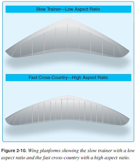 Wing loading is a term associated with total weight being carried by the wing in relation to the size of the wing. It is the amount of load each square foot of the wing must support. Wing loading is found by dividing the total weight of the aircraft, in pounds, by the total area of the wing, in square feet. For example, the wing loading would be 5.0 pounds per square foot when 1,000 pounds total weight for a two-seat WSC aircraft with two people is supported by a 200 square foot wing. If fl ying the same wing with one person and a lighter total weight of 500 pounds, the wing loading would be 2.5 pounds per square foot. In the small, high performance wing of 140 square feet loaded at 1,000 pounds, wing loading would be 7.1 pounds per square foot. Gliding fl ight is fl ying in a descent with the engine at idle or shut off. For example, use a glide ratio of 5, which is fi ve feet traveled horizontally for every foot descended vertically. Glide ratios vary signifi cantly between models. |
| ©AvStop Online Magazine Contact Us Return To Books |