
![]()
|
|
||
CHAPTER 2. Aerodynamics Longitudinal Axis— Roll Turning is initiated by rolling about the longitudinal axis, into a bank similar to an airplane using aileron and rudder control. To turn, shift the weight to the side in the direction of the turn, increasing the weight on that side. This increases the twist on that side while decreasing the twist on the other side, similar to actuating the ailerons on an airplane. The increased twist on the side with the increased weight reduces the AOA on the tip, reducing the lift on that side and dropping the wing into a bank. The other wing, away from which the weight has been shifted, decreases twist. The AOA increases, increasing the lift on that wing and thereby raising it. Thus, shifting the weight to one side warps the wing (changes the twist) to drop one wing and raise the other, rolling the WSC aircraft about the longitudinal axis. [Figure 2-24] More details on the controls that assist wing warping are covered in chapter 3, which should be considered with use of the controls in the takeoff, landing, and fl ight maneuvers sections of this handbook. 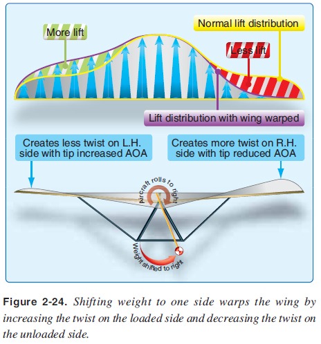 Vertical Axis— Yaw The WSC wing is designed to fl y directly into the relative wind because it does not provide for direct control of rotation about the vertical axis. Stability and Moments A body that rotates freely turns about its CG. In aerodynamic terms for a WSC aircraft, the mathematical value of a moment is the product of the force times the distance from the CG (moment arm) at which the force is applied. Typical airplane wings generally pitch nose down or roll forward and follow the curvature of the upper airfoil camber creating a negative pitching moment. One of the reasons airplanes have tails is to create a downward force at the rear of the aircraft to maintain stabilized fl ight, as explained in greater detail in the Pilot’s Handbook of Aeronautical Knowledge. The WSC wing is completely different and does not need a tail because of two specifi c design differences—a completely different airfoil design creating a more stable airfoil and lifting surfaces fore and aft of the CG, similar to the airplane canard design. WSC Unique Airfoil and Wing Design As shown in Figure 2-2, the WSC airfoil has the high point signifi cantly farther forward than does the typical airplane airfoil. This makes the center of lift for the airfoil farther forward and creates a neutral or positive pitching moment for the airfoil. Most WSC airfoils have this unique design to minimize negative moments or pitch down during fl ight. Additionally, the design of the complete wing is a unique feature that provides stability without a tail. To understand the WSC aircraft pitch stability and moments, examine the wing as two separate components—root chord and tip chord. Trim—Normal Stabilized Flight In Figure 2-25A, during normal unaccelerated fl ight at trim speed, the lift at the root (LR) times the arm to the root (AR) equals the lift of the tip (LT) times the arm to the tip (AT). (LR x AR) + (LT x AT) = 0 LR + LT = Total Lift of the Wing (LW) Adding all the lift from the wing puts the center of lift of the wing (CLW) directly over the CG for stabilized fl ight. [Figure 2-25A] If the pilot wishes to increase the trim speed, the CG is moved forward. This is done by moving the hang point forward on the wing. Similarly, to reduce the trim speed, the hang point/CG is moved rearward on the wing. 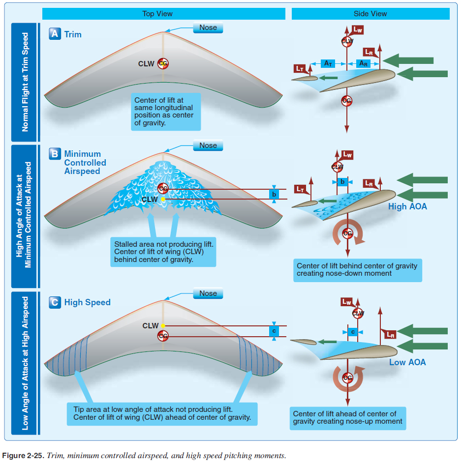 High Angles of Attack In Figure 2-25B, if the wing AOA is raised to the point of minimum controlled airspeed at which the wing begins to stall towards the center of the wing (root area), the lift in this area decreases dramatically. The CLW moves back a distance “b” creating a moment to lower the nose. Therefore, the center of lift moves behind the CG at higher angles of attack, creating a nose-down stabilizing moment. The average lift coeffi cient verses AOA is shown for this minimum controlled airspeee root area is partially stalled and the tips are still fl ying. The specifi c stall characteristics of each wing are different and this stall pattern shown here id in Figure 2-26. Ths used for example. 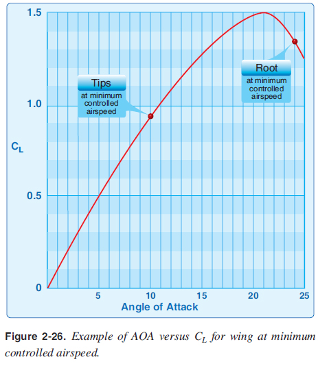 |
| ©AvStop Online Magazine Contact Us Return To Books |
