
![]()
|
|
||
| CHAPTER 3. Components and Systems
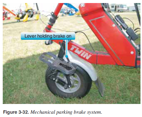
Structure Similar to the wing, the carriage is designed with a number of structural triangles for optimum strength and minimum weight. Each manufacturer and model have specific details that vary, but the carriage structure is typically a mast, keel, and front tube that form the main triangle components of the carriage structure with the wing attachment at the top of the mast. A seat frame attached to the mast and keel provides rigidity to the main components while providing structure for the pilot and passenger. [Figure 3-26] 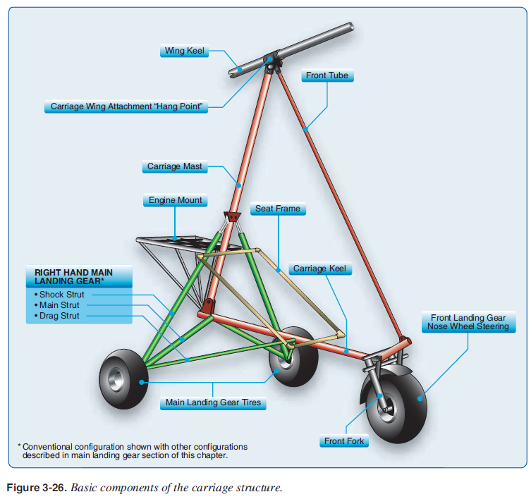 Landing struts attached to the rear wheels provide structure for the main landing gear, and a front fork provides the landing gear structure for the front wheel. An engine mount attaches to the mast, providing structure for the propulsion system to attach to the carriage. [Figure 3-26] Landing Gear The landing gear provides support to the WSC aircraft on the ground and absorbs the shock to reduce the stresses on the pilot and the aircraft during landings. The landing gear is made up of the front wheel, which has a lighter load and is used for steering, and the main or rear landing gear, which takes most of the load for the aircraft. [Figure 3-26] The front steering fork for the nosewheel has foot rests attached that the pilot uses for steering the WSC aircraft on the ground. Besides ground steering, the foot controls are similar to driving a car, left foot pedal is brakes on the ground only, and right foot is throttle and power on the ground and in fl ight. [Figure 3-27] The front fork typically has camber so it naturally tracks in the direction of travel similar to a motorcycle front fork. 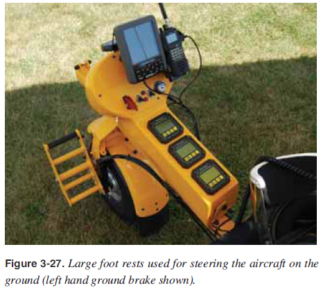 For training, a second steering control is installed with a connecting rod so the instructor can sit in back and steer the carriage on the ground using the nosewheel. [Figure 3-28] Steering dampers are sometimes used to stabilize the front wheel from shimmying at higher speeds during takeoff and landing. [Figure 3-29] The front wheel sometimes has shock absorbers or the tire itself can act as the shock absorber. The front wheel typically has a disk or a drum brake, mechanical or hydraulic. [Figures 3-30 and 3-31] A front brake is lighter and simpler than rear brakes, but some carriage brake systems utilize the rear brakes. 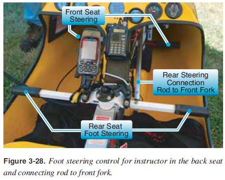 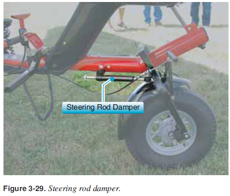 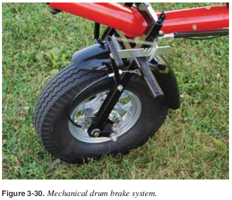 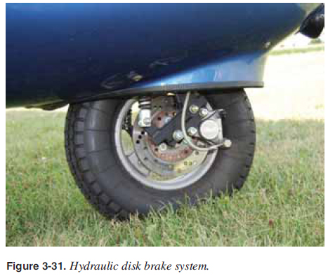 A parking brake is extremely useful for securing the aircraft
on the ground without needing chocks for securing the
aircraft before takeoff and after landing. A number of parking
brake systems are utilized by different manufacturers.
[Figure 3-32]
 The main landing gear is the two rear wheels of the WSC aircraft. Since the center of gravity (CG) is much closer to the rear wheels, most of the weight for the aircraft is carried on the rear wheels for taxi, takeoff, and landings. There are a number of different confi gurations for the main gear. A conventional confi guration has two separate systems for each rear wheel. Each side is two structural triangles, one horizontal and one vertical. The horizontal triangle consists of a drag strut from the wheel forward to the keel or forward structure to maintain the wheel’s fore and aft position, and the main landing gear strut. Both the main and the drag struts can pivot about the attachment to the keel as part of the shock system. The vertical triangle consists of the main landing strut and the shock strut attached to the wheel and up to the keel structure [Figure 3-36] or other structure such as the engine mount shown in Figure 3-33, which houses the compressed nitrogen and oil “oleo” shock absorber. 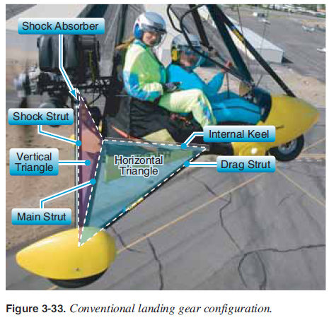 There are a number of other main landing gear confi gurations and shock absorbing systems such as wire bracing with bungee cord shocks [Figure 3-34], fiberglass or flexible (fiberglass or steel) main gears with no struts [Figure 3-35], and any variation of these. Carriages designed for faster speeds may have streamlined landing gear systems. [Figures 3-36 and 3-37] 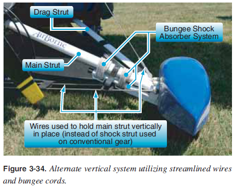 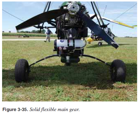 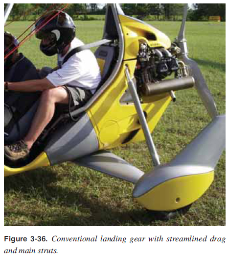 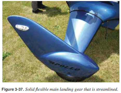 As discussed in the nosewheel section, the carriage can have main landing gear brakes on both main landing gear wheels that can be drum or disk and controlled by mechanical or hydraulic actuation. Each manufacturer has different designs and options. Tires can also assist as shock absorbers for landings. Large tundra tires add signifi cant shock absorbing capability and are used for operations on soft fi elds, rough fi elds, and sand. [Figure 3-38] Generally, the faster WSC aircraft used for airport operations have narrower tires to eliminate drag. 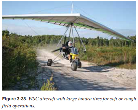 |
| ©AvStop Online Magazine Contact Us Return To Books |
