
![]()
|
|
||
| CHAPTER 3. Components and Systems
Electrical Systems WSC aircraft are typically equipped with a 12-volt direct current (DC) electrical system. A basic WSC aircraft electrical system consists of a magneto/generator, voltage regulator, battery, master/battery switch, and associated electrical wiring. Electrical energy stored in a battery provides a source of electrical power for starting the engine and other electrical loads for the WSC aircraft. The electrical system is typically turned on or off with a master switch. Turning the master switch to the on position provides electrical energy from the battery to all the electrical equipment circuits with the exception of the ignition system. Equipment that commonly uses the electrical system energy includes:
Fuses or circuit breakers are used in the electrical system to protect the circuits and equipment from electrical overload. Spare fuses of the proper amperage should be carried in the WSC aircraft to replace defective or blown fuses. Circuit breakers have the same function as a fuse but can be manually reset, rather than replaced, if an overload condition occurs in the electrical system. Placards at the fuse or circuit breaker panel identify the circuit by name and show the amperage limit. An ammeter may be used to monitor the performance of the electrical system. The ammeter shows if the magneto/ generator is producing an adequate supply of electrical power. It also indicates whether or not the battery is receiving an electrical charge. A voltage meter also provides electrical information about battery voltage, an additional status of the electrical system. Ballistic Parachute An additional safety system available is a ballistic parachute system. In the case of a structural failure because of a mid-air collision or an engine out over hostile terrain such as a forest, the ballistic parachute provides an added safety system. The parachute is sized so that when used, the complete aircraft comes down under canopy. Details of ballistic parachute system use are covered in more detail in Chapter 13, Abnormal and Emergency Operations. When the system is activated, a rocket shoots out, pulling the parachute system to full line stretch, and forcing the parachute out and away from the carriage and wing. The preferred point of attachment for the parachute is on top of the wing at the hang point. This allows the WSC aircraft to descend level and land on the wheels, helping to absorb the shock. This requires routing from the chute to the top of the wing with “O” rings to be able to remove this routing to easily take the wing off the carriage. Alternate attach points where there is no routing to the top of the wing are the mast and engine attachment points; however, this has the WSC aircraft descending nose down when activated. The ballistic parachute canister can be mounted in a number of locations on the WSC, typically on the carriage pointed sideways to avoid entanglement with the propeller. The actuation handle is mounted in the fl ight deck for pilot use when needed. [Figures 3-41 and 3-42] 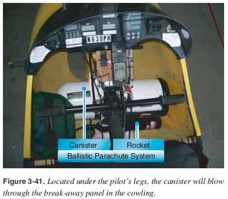 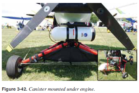 |
| ©AvStop Online Magazine Contact Us Return To Books |
