
![]()
|
|
||
| CHAPTER 3. Components and Systems
Roll Control System Control bar movement from side to side controls the roll about the longitudinal axis. The wing attachment hang point allows the carriage to roll around the wing keel. Thus, it can also be looked at from the carriage point of view, when the control bar is moved side to side, the wing rotates around the wing keel relative to the carriage. [Figures 2-31 and 3-19] 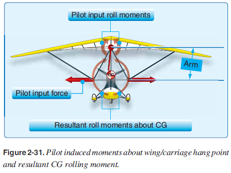 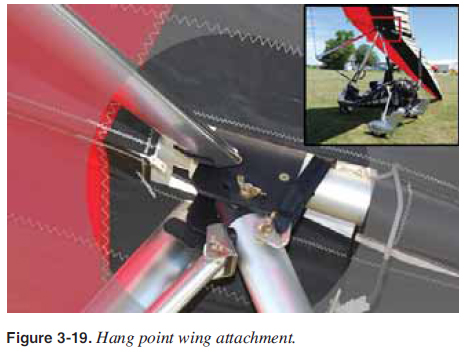 It would fi rst appear that moving the control bar to one side, thus shifting weight to the opposite side, could alone bank the aircraft. It is true that shifting weight to the right would naturally bank the aircraft to the right and put it into a right hand turn. However, the weight alone is not enough to provide adequate roll control for practical fl ight. As weight is moved to one side, the keel is pulled closer to that side’s leading edge. The actual keel movement is limited to only 1 to 2 inches each side of center. However, this limited keel movement is suffi cient to warp the wing, changing the twist side to side (as discussed earlier in the aerodynamics section) to roll the aircraft [Figure 2-24] by changing the lift side to side. Simply, the shifting of weight from side to side pulls the keel toward the leading edge on that side and warps the wing to roll the aircraft. 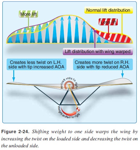 Besides the keel shifting relative to the leading edges and crossbar, overall roll control is adjusted by the designers to fi t the mission of the wing through sail material/stiffness, leading edge stiffness/fl exibility, amount of twist, amount of travel the keel is allowed, airfoil shape, and the planform of the wing. [Figures 3-20 and 3-21] 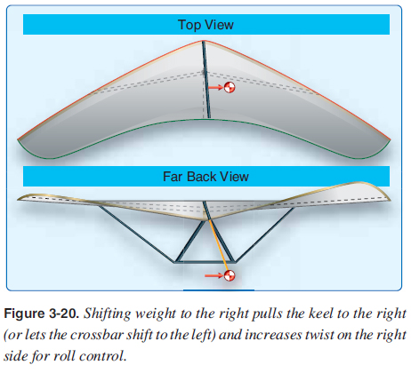 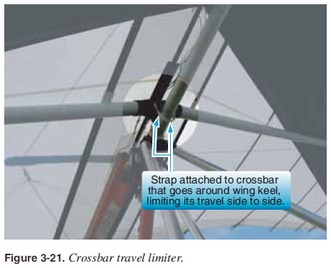 Trim Systems There are a number of trim systems to relieve the control pressures for pilots to fl y at different “hands off” trim speeds. Ground adjustable trim allows the pilot to adjust the trim speed of the wing on the ground and remain at one speed during fl ight, while fl ight adjustable trim systems can change the trim speed in fl ight. Ground Adjustable Trim Systems The most common ground adjustable trim system, and typical of most aircraft, is moving the wing attachment hang point forward for faster trim speeds and aft for slower trim speeds. Each manufacturer has different hardware, but the basics of sliding the carriage wing hang point forward and backward on the keel is similar for all. As an example, moving the hang point at the furthest aft position to the furthest forward position could speed the wing up 20 knots. This in turn moves the control bar position back to a new “hands off” trim speed. Another less commonly used method of increasing trim speed is to increase tension on the crossbar by pulling it back further, slightly increasing the nose angle and reducing twist. This increases the angle of attack (AOA) of the tips producing more lift, and it lowers the nose to a higher trim speed. This is a typical in-fl ight trim adjustment for high performance hang gliders. The roll control is diminished with this faster and stiffer wing. Ground adjustable trim systems are described in the Pilot's Operating Handbook (POH) for each aircraft. Different loads may require different pitch settings. |
| ©AvStop Online Magazine Contact Us Return To Books |
