CHAPTER 3 - EMPTY WEIGHT CENTER OF GRAVITY
CHAPTER 3 - EMPTY WEIGHT CENTER OF GRAVITY
Weighing aircraft with accurately calibrated scales is the only sure
method of obtaining an accurate empty weight and c.g. location. The use
of weight and balance records in accounting for and correcting the aircraft
weight and balance location is reliable over certain periods of time. Over
extended intervals, however, unknown service weight pickup and other factors
will render the basic weight and c.g. data inaccurate. For this reason,
periodic aircraft weighings are desirable. Aircraft may also be weighed
when major modifications or repairs are made, when the pilot reports unsatisfactory
flight characteristics such as nose or tail heaviness, and when recorded
weight and balance data are suspected to be in error. The pilot or owner
may never actually weigh an aircraft but he should be aware of the general
procedure and requirements.
| WEIGHING EQUIPMENT
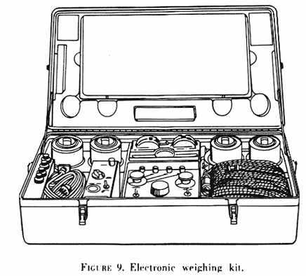
The type of equipment which is used to weigh aircraft will vary with
the aircraft size. Light aircraft may be weighed on commercial type platform
scales. Large aircraft are usually weighed with electronic weighing sets
(fig. 9). In any case, the individual scale or the electronic cell should
have a capacity rating suitable for the size of the aircraft - for instance,
three scales with 5,000 lb. ratings would be suitable to weigh a 10,000
lb. aircraft while an electronic cell set with cells of 50,000 lb. capacity
would be needed for a 100,000 lb. aircraft. Only weighing equipment that
is maintained and calibrated to acceptable standards should be used to
weigh aircraft.
Jacks are ordinarily used for leveling an aircraft. Care should be taken
to use jacks of sufficient capacity and extension for the particular aircraft.
Adapters for jack points or blocks for wheels are necessary to prevent
the aircraft from moving or falling when it has been raised off the ground. |
 |
Accurate spirit levels are used to assure that the aircraft is in a level
position. Large aircraft are often checked for level by the use of a surveyor's
transit. Plumb bobs, straight edges, and chalk lines are some other items
of auxiliary equipment used during the weighing process.
WEIGHING PROCEDURE
The aircraft should be weighed in accordance with instructions in the
manufacturers' manuals or other pertinent technical data. Typical procedures
include:
a. The aircraft should be cleaned inside and out.
b. The aircraft equipment should be checked against the equipment list
section of the weight and balance record (fig. 21).
This list should have been updated to account for all equipment changes
made after the list was initially established by the manufacturer. All
items which are not included as fixed equipment on the updated list should
be removed for the empty weight check.
c. Fuel tanks should be drained in accordance with the manufacturer's
instructions. In lieu of specific instructions, the tanks can be drained
until the tank quantity gauges read "zero" or empty in level flight attitude.
The amount of fuel remaining in the tanks, lines, and engines is termed
"residual fuel" and it is to be included in the empty weight. In certain
cases, it may not be feasible to drain the fuel tanks; if this is so, fill
the tanks to capacity. The weight of the fuel in the tanks should then
be calculated and later subtracted from the total weight to obtain the
empty weight.
d. Unless otherwise noted in the aircraft specification,
the oil system
should be completely drained through the normal drain ports. Under these
conditions, the amount of oil remaining in the tanks, lines, and engine
is termed "residual oil" and it will be included in the empty weight. When
the aircraft is weighed without draining the oil, the tanks should be filled
to capacity. The oil weight can then be calculated at a standard weight
of 7.5 lbs./gal.
e. Reservoirs or tanks containing hydraulic fluid, anti-icing fluid
and other liquids which are considered part of the empty weight should
be filled to capacity.
f. Generally, all aircraft are weighed in a level position. This means
the aircraft is placed in an attitude in which its longitudinal and lateral
axes are parallel to a horizontal surface. leveling devices such as leveling
lugs and jig-located brackets and plates have been accurately installed
on the aircraft by the manufacturer to facilitate the leveling procedure.
The methods used to level specific aircraft vary with the type of aircraft
and the leveling instructions provided by the manufacturer.
1. Jacks which are used for leveling should never be employed on the
aircraft other than at the specified jacking points. If wing and fuselage
jacks are used to level the aircraft, it may be necessary to prevent the
gear shock struts from extending when the aircraft is raised. The manufacturer's
instructions will indicate the appropriate procedures in this case.
2. During the leveling procedure, extreme care should be exercised to
avoid side loads which may cause the aircraft to slip off the jacks. When
raising the aircraft with two wing or two main landing gear jacks, they
should be actuated simultaneously in order to maintain the aircraft in
a laterally level attitude. General instructions for various types of aircraft
are as follows:
(a) Nosewheel oleo struts or tires may be inflated or deflated to level
the aircraft. They may also be used to obtain an approximately level position
prior to jacking the aircraft.
(b) A hoist or jack should be employed to level tailwheel aircraft when
the aircraft is too heavy to raise the tail manually.
(c) Normally, the smaller type of rotary wing aircraft incorporating
skids rest in approximately level position. Larger rotary wing aircraft
with oleo struts may be placed in the level position by inflating or deflating
the struts.
| (d) A float plane may be weighed by placing the floats
on four scales with suitable blocks to obtain concentrated reaction points.
Care must be taken to prevent damage to the floats from this concentrated
loading. Ordinarily, the normal landplane leveling points are used. The
floats are not necessarily level. Amphibians can be weighed with the landing
gear down and on the scales.
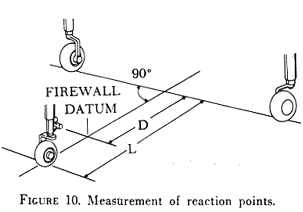
g. Once the aircraft is in the level position, it is necessary to measure
and record dimensions. Three horizontal dimensions need to be measured
to determine the horizontal location of the c.g. of the aircraft as weighed.
In some cases, these dimensions can be obtained from aircraft records.
When the landing gear wheels are used as weighing (reaction) points, the
three dimensions to be determined are as follows (see fig. 10): |
|
1. The horizontal distance from the reference datum to some known jig
point. This dimension, for small aircraft, is usually zero because the
reference datum is an easily identified location, such as the firewall
or wing leading edge. It is particularly important to determine such a
dimension if the datum is located ahead of the nose of the aircraft.
2. The distance from the jig point to a lateral line passing through
the main gear reaction points. This measurement should be made along a
line which is parallel to the longitudinal axis of the aircraft.
3. The wheel base or distance between the main and forward or aft reaction
points.
Measuring these distances can be accomplished by projecting the required
points to the hangar floor. To project the jig point to the hangar floor,
a plumb bob may be suspended from the center of the jig point so that the
plumb bob is approximately one-half inch above the floor. When the swing
of the bob dampens, a cross mark is made on the floor directly under the
tip of the plumb bob. The main reaction points are projected to the floor
in the same manner. After marking the crosses for the two main gear points,
a chalked string is stretched between them. The string is then snapped
to the floor, leaving a clear straight chalkline between the main reaction
points. The nose or tail reaction point is projected to the hangar floor
in a similar manner (fig. 10).
After these points are projected to the floor it is a simple matter
to measure the required dimensions. When measuring these distances, it
is necessary that the tape be parallel to the centerline of the aircraft.
Measurements made from the main reaction points are taken perpendicular
to the chalkline joining these two points. When fuselage and wing jack
points are used as reaction points in weighing the aircraft, it is unnecessary
to measure dimensions. These points will remain fixed and their moment
arms may be found in the aircraft records. Care must be taken to use the
fixed reaction points indicated in the records for the particular aircraft
being measured. Because of manufacturing tolerances, and minor model changes,
the fixed reaction points are not necessarily identical for all aircraft
of a particular type.
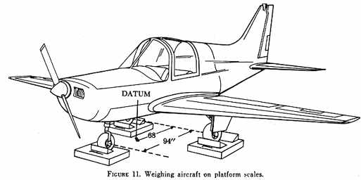
| Weighing procedures may vary with the aircraft and the
type of weighing equipment employed. The weighing procedures contained
in the manufacturers' manuals should be followed for each particular aircraft.
The following general instructions illustrate a common method and some
of the typical precautions (see fig. 11):
a. Aircraft are weighed in closed hangars to avoid vibrations or lift
forces which would otherwise be caused by air flowing over the lifting
surfaces. Such vibrations or aerodynamic forces would result in fluctuating
scale readings and increase the possibility of error. |
|
b. The aircraft must be dry before it is weighed. An aircraft should
never be weighed immediately after it has been washed.
c. The aircraft should be weighed in the level attitude. If the main
wheels are used as reaction points, the brakes should not be set - resultant
side loads on the scales or weighing units may cause erroneous readings.
d. The aircraft should be raised simultaneously on all reaction points,
especially when using electronic weighing equipment. When the aircraft
is supported at the weighing reaction points only, and is in the level
position, scale readings may be obtained (fig. 11).
e. Several readings are taken for each reaction point and the average
reading is entered on the aircraft weighing form.
f. Before the aircraft is lowered, it is necessary to make certain that
all necessary measurements and scale readings have been obtained and recorded.
The scales or cells should be rechecked for errors and compared to the
calibration errors recorded before the weighing process. Appropriate calibration
corrections or reweighing may then be necessary.
g. When data for comparison is available, an attempt should be made
to verify the results obtained from each weighing. Verification may be
made by comparing results with a previous weighing of an aircraft of the
same model.
FINDING CENTER OF GRAVITY
After the necessary dimensions and weights have been obtained, the empty
weight and the empty c.g. can be calculated. Empty weight is the total
of the three scale readings after subtracting the weight of tare items
plus or minus calibration errors. This weight is important for subsequent
calculation of maximum weight and also is a necessary factor in the determination
of c.g.
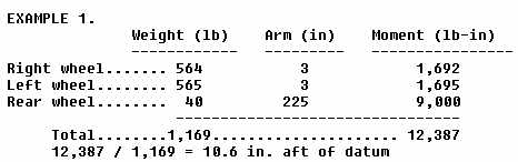
Center of gravity computations may be accomplished by several methods.
Fundamentally, the c.g. is the point at which all the weights of the aircraft
can be considered to be concentrated. The average location of the weights
can, therefore, be obtained by dividing the total moments (wt. x arm) by
the total weight. The process then involves multiplying each measured weight
by its arm to obtain a moment and adding the moments.
 |
|
Extra care must be taken in these types of empty weight calculations
if one or more of the arms is located ahead of the datum. In this event,
the algebraic sign of the arm and moment will be negative. It should be
remembered that a positive number (the weight) times a negative number
(the arm) results in a negative number (the moment). Following the multiplication
step, additional care must be taken when adding wheel moments to obtain
total moments and when dividing total moments by total weight to obtain
c.g. In all these mathematical operations, the significance of the algebraic
sign must be observed.
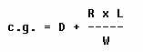
The c.g. can also be obtained by the use of a special formula:
This formula and others which are applicable to nosewheel aircraft and
those with the datum located in an aft position are shown in figure
12, together with definitions of the symbols involved. The use of these
formulas simplifies the calculations in several ways. In effect, the datum
is mathematically moved to the main gear by this process, resulting in
relatively small moments which are easy to handle in weight and balance
calculations. A major benefit of the use of these formulas is the elimination
of multiplication steps that involve negative arms and negative moments.
A solution to the problem in example 1 by use of the c.g. formula is
shown in figure 13. The answer is the same but the
process is somewhat simplified because the step of multiplication of each
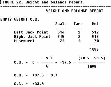
weight and arm has been eliminated. The solution shown in figure
13 shows how the information is entered in the empty weight c.g. part
of a weight and balance report form.
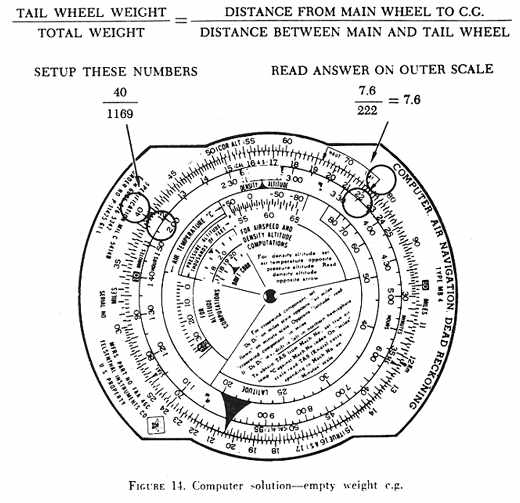
An aeronautical computer (fig. 14) can be used
to further simplify the problem when the formula is converted into a proportion
form:
EXAMPLE 2.
The computer solution (7.6 in.) is then added to the arm of the main
wheels (3 in.) to obtain the c.g. location (10.6 in.) aft of datum.
PERCENT OF MEAN AERODYNAMIC CHORD (MAC)
Expression of the c.g. relative to the MAC is a common practice. The
c.g. position is expressed as a % MAC (percent of the mean aerodynamic
chord) and the c.g. limits are expressed in the same manner (fig.
15).
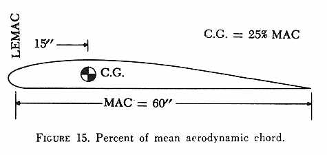 |
The relative positions of the c.g. and the aerodynamic center or center
of lift of the wing have critical effects on the flight characteristics
of the aircraft. Consequently, relating the c.g. location to the chord
of the wing is convenient from a design and operations standpoint. Normally,
an aircraft will have acceptable flight characteristics if the c.g. is
located somewhere near the 25% average chord point. This means the c.g.
is located one-fourth of the total distance back from the leading edge
of the average wing section. Such a location will place the c.g. forward
of the aerodynamic center for most airfoils. |
The mean aerodynamic chord is established by the manufacturer. If the
wing is not swept and has a constant chord, the straight line distance
from leading edge to trailing edge (the chord) would also be the MAC. However,
if the wing is swept or tapered, the mean aerodynamic chord is more complicated
to define, and the manufacturer's description is the only reliable description
for weight and balance purposes. The MAC can be defined as the "chord of
an imaginary airfoil which has the same aerodynamic characteristics as
the actual airfoil."
In summary, the MAC is established by the manufacturer who defines its
leading edge (LEMAC) and its trailing edge in terms of inches from datum.
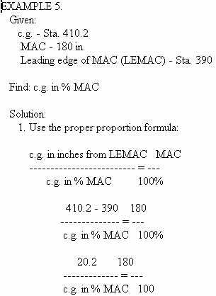
The c.g. location and various limits are then expressed in percentages
of the MAC. The following are typical computations to use in finding the
c.g. location in relation to MAC:
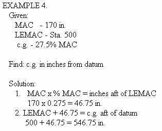
Use the following method to convert locations expressed in % MAC to
locations expressed in inches from datum:
Proportion formulas can be readily adapted to the conversion of % MAC
to inches from datum.
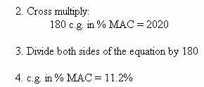
A typical problem solved by the use of a proportion formula follows:
NOTE - Steps 2 and 3 can be eliminated by the use of an aeronautical
computer to solve the proportion in step 1 (fig. 16).
With the use of the proportion formula presented above, the expression
of a location can be easily changed from % MAC to "inches from datum."
The following example illustrates a typical problem with a computer solution.
EXAMPLE 6.
Given:
c.g. - 20% MAC
MAC - 175 in.
LEMAC - Sta. 380
Find: c.g. in inches from datum
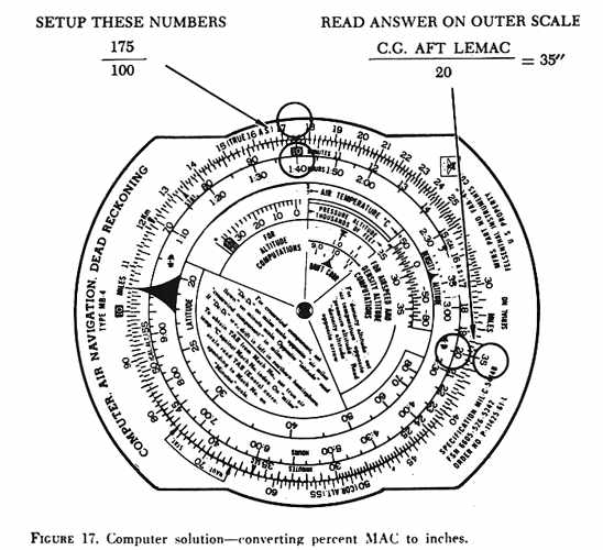
Solution:
1. Set up the proportion on the computer (fig. 17).
2. Add to LEMAC:
380 + 35 = 415.0 in.
NOTE - It is easy to check the computer solution (fig.
17) by arithmetical means. The arithmetical solution is:
1. MAC x % MAC:
175 x 0.20 =
35.0 in. (c.g. aft of LEMAC)
2. Add to LEMAC:
380 + 35.0 =
415.0 in.
FAA written tests often make use of a graphic presentation of the information
needed to solve center of gravity problems (fig. 18).
The following is a typical example which combines some of the principles
explained in this chapter:
|
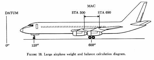 |
EXAMPLE 7.
Given: The aircraft in figure 18 was weighed in the
empty weight condition and was found to have the following readings at
the three scales:
Pounds
Nosewheel weight......... 20,500
Right wheel weight....... 70,000
Left wheel weight........ 70,500
Find: The c.g. location expressed in % MAC.
Solution:
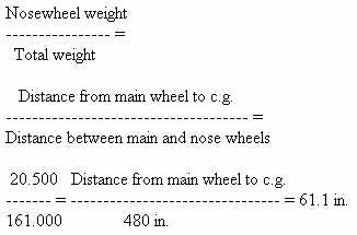
1. Find c.g. in inches from datum using proportion formula:
2. 600.0 - 61.1 = 538.9 in. aft of datum.
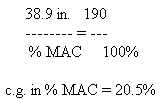
3. 538.9 - 500 = 38.9 in. aft of LEMAC.
4. Convert to % MAC by using the proportion formula (see EXAMPLE
5):
By using information on the diagram (fig. 18), we
can determine c.g. limits in inches from datum when they are expressed
in % MAC.
EXAMPLE 8.
Given: The aircraft illustrated in figure 18 has its forward c.g. limit
located at 12% MAC and its rearward c.g. limit located at 32% MAC.
Find: What are the c.g. limits of this aircraft in inches from datum?
Solution:
1. Multiply MAC times the given percentages (in decimal form)
190 x 0.12 = 22.8 in.
190 x 0.32 = 60.8 in.
2. Add to LEMAC:
Forward limit (500 + 22.8) = 522.8 in. aft of datum.
Aft limit (500 + 60.8) = 560.8 in. aft of datum.
AIRCRAFT MODIFICATIONS
After alteration of an aircraft or after the removal or installation
of equipment, it is necessary to establish that the authorized weight and
c.g. limits as shown on the FAA aircraft type certificate data sheet or
specification are not exceeded when the aircraft is properly loaded. The
owner should assure that this determination has been made and that the
repair agency has entered appropriate changes in the weight and balance
records of the aircraft. If equipment alterations are made without preparation
of weight and balance records, all subsequent calculations by operating
personnel would be in error. The effect of weight and balance calculation
errors upon the safety of flight is potentially tragic; therefore, strict
adherence to regulations and ethical practices by the owner and repair
agency is essential.
The original basis for weight and balance calculations pertaining to
alterations of the aircraft are the FAA aircraft type certificate data
sheets or specifications. They provide the essentials for calculation of
c.g. changes due to aircraft modifications: weights, arms, and limitations.
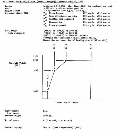
These essentials are illustrated in the excerpts from a typical FAA aircraft
type certificate data sheet shown in figure 19. It
should be noted that all details listed in the type certificate data sheet
may not be appropriate for an aircraft which has been modified.
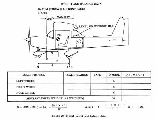
The manufacturer is required to provide documents which show the certificated
empty weight and c.g. for each new aircraft. This weight and balance data
may also include a schematic diagram which illustrates the fixed dimensions
for all aircraft of the particular model (see fig. 20).
The continued validity of weight and balance records during the life of
the aircraft depends upon the maintenance of a series of similar documents
which show the calculations for each successive weight change. This series
of documents starts with the manufacturer's data and continues in chronological
order to the latest weight and balance report. When a new weight and balance
report is prepared for an aircraft, the previous report should be marked
superseded and reference the date of the new document. This would preclude
the necessity to search for the current report.
Data prepared by the repair agency for each modification should indicate
that the maximum weight of the aircraft will be within the maximum allowable
weight with anticipated loads. The new empty weight is derived from the
empty weight recorded on the most recent weight and balance report plus
the weight of the items added, minus the weight of items removed. When
load items are added to this new empty weight, the total weight can be
compared to the limit listed in the aircraft specifications.
WEIGHT AND BALANCE REPORT
Detailed instructions on repair and alteration procedures are contained
in Advisory Circulars 43.13-1A and 43.13-2. Generally, the repair agency
should prepare weight and balance data to show that the aircraft does not
exceed maximum weight limits, in various load combinations, after the alteration
has been made. The owner should assure that the data has been provided
by the repair agency.
The repair agency also includes in the weight and balance data, information
showing that the c.g. of the aircraft (usually in the fully loaded condition)
falls between the specified c.g. limits when loaded in one of the extreme
conditions. The weight and balance extreme conditions represent the maximum
forward and rearward c.g. position for the aircraft. The computations are
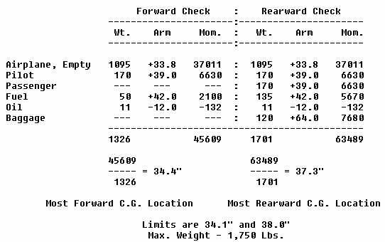
known as the forward and rearward extreme conditions check.
When a forward extreme condition check is made, the objective is to
establish that neither the maximum weight limit nor the forward c.g. limit
listed in the aircraft specifications is exceeded. Normally, in the case
of a four place airplane, this check must be made assuming both front seats
are occupied and the rear seats empty. If the baggage compartment is in
the rear, it is also assumed to be empty. If the fuel tanks are located
forward of the forward limit, they are assumed to be full. If they are
located aft of the forward limit, they are assumed to be empty. However,
a minimum fuel load is always included in the calculation. This minimum
fuel load for a small aircraft with reciprocating engines is calculated
by:
 |
|
For jet engine aircraft, the minimum fuel for extreme conditions check
is specified by the manufacturer. When a rearward weight and balance check
is made, the objective is to establish that neither the maximum weight
limit nor the rearward c.g. limit listed in the aircraft specifications
is exceeded.
The loading conditions are obviously opposite to those used for the
forward check. For a typical four seat airplane, the rearward check is
made with one pilot, maximum rear passengers, maximum rear baggage, and
full fuel loaded in tanks behind the rear c.g. limit. After making these
checks, the repair agency completes records in the form of a weight and
balance report, loading schedule, or placard to inform the owner and operator
about the permissible load combinations.
 |
|
A list of the equipment (fig. 21) included in the
aircraft during calculation of the certificated empty weight may be found
in either the approved airplane flight manual or the weight and balance
report. The repair agency should enter in the weight and balance report
all required, optional, and special equipment installed in the aircraft
at the time of weighing and when equipment changes are made. The owner
should assure that the person making an equipment change completes an entry
on the equipment list to indicate items added, removed, or relocated. The
entry should also include the date accomplished, identity of the person
making the change, and certificate number of that person.
Suggested methods of tabulating the various data and computations for
determining the c.g., in the empty weight condition and the forward and
aft extreme loaded conditions, are given in figure 22.
Ballast is sometimes permanently installed for c.g. balance purposes
as a result of installation or removal of equipment items and is not used
to correct a nose-up or nose-down tendency of an aircraft. It is usually
located as far aft or as far forward as possible in order to bring the
c.g. position within acceptable limits with a minimum of weight increase.
WEIGHT AND BALANCE EXTREME CONDITIONS
