Aviation has been one of the most dynamic of industries since its beginning. New aircraft are continually being developed and always represent an improvement over older models. Improvements in design have, in many cases, tended to increase aircraft complexity. However, considerable effort has been spent to keep the new designs simple so that operations and maintenance procedures can be accomplished by the average airman. In accordance with this design philosophy, weight and balance engineers have developed some simplified methods, which they have applied to the weight and balance problems of most modern aircraft. Index numbers and graphic presentation of limits are features of simplified methods in common use.
INDEX NUMBERS
The use of index numbers and a reduction factor greatly simplifies weight and balance calculations, especially for large aircraft. The index is a moment divided by a reduction factor and may be found by this formula:
Weight x Arm (moment)
Index = ---------------------
Reduction factor
The moments with which we are concerned on transport aircraft and the larger general aviation aircraft will be large numbers because of the large weights and arms which are involved. In a transport aircraft, a fuel tank located at station 500 which is loaded with 5,000 pounds of fuel would represent a moment of 2,500,000. This moment when divided (or reduced) by a reduction factor of 10,000 becomes a more manageable index of 250.0. The same problem exists to a smaller degree for general aviation aircraft. In this case, a reduction factor of 100 or 1,000 produces manageable numbers. A simple way to change the moment into the index is to count the number of zeros in the reduction factor and move the decimal point of the moment the same number of places to the left.
Reduction factor - 10,000 (4 zeros)
Moment
- 2,500,000 move the decimal point
4 places to the left
250.0000 = Index of 250.0
If the moment is a number with sufficient zeros, for instance a moment of 5,600,000, simply cross out the same number of zeros as you find in the reduction factor.
For example:
Reduction factor - 1,000 (3 zeros)
Moment
- 5,600,000 cross out 3 zeros
5,600,000 = Index of 5600
Follow the opposite procedure when changing from index numbers to moments:
Reduction factor - 100 (2 zeros)
Index
- 321.2 move decimal 2 places to the right
32,120.0 = Moment of 32,120.0
You will notice that the simplified steps above would not be quite as easy if the reduction factors were not numbers such as 100, 1,000, or 10,000. If a reduction factor such as 7,750 were used, the process would be more complicated. Therefore, reduction factors are usually standardized to be either 100, 1,000, or 10,000 for a particular aircraft. Reduction factors of 20,000 or 40,000 are used for some large aircraft in order to tailor the index numbers to a particular weight and balance system. When these reduction factors are used, the process of decimal point movement must be combined with a division or multiplication step.
Reduction factor - 20,000 (4 zeros)
Moment - 7,200, cross out 4 zeros and divide by 2
7,200,000
--------- = Index of 360.0
2
Reduction factor - 30,000 (4 zeros)
Index
- 492.1
move decimal 4 places to the right and
multiply by 3
4,921,000.0 x 3 = Moment of 14,763,000
It should be apparent that the index number system can be applied to total aircraft moments as readily as to individual load items. This principle is illustrated in the following example:
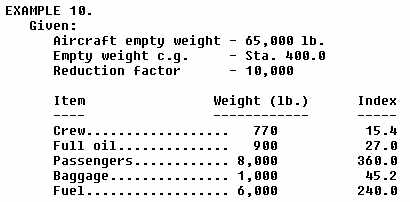
EXAMPLE 9.
Given:
Aircraft total weight - 105,000 lb.
c.g. (average arm) - Sta. 500
Reduction factor - 10,000
Find: Total weight index
Solution:
Weight x Arm
Use index formula = ----------------
Reduction factor
105,000 x 500
------------- = 5250.0
10,000
Total weight index = 5250.0
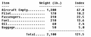
In typical problems involving index numbers, the weights and index numbers
of particular aircraft load items are given and the fully loaded c.g. must
be found.
|
Find: What is the c.g. location when the aircraft is loaded with the items given above?
Solution:
1. Find empty weight index by use of formula:
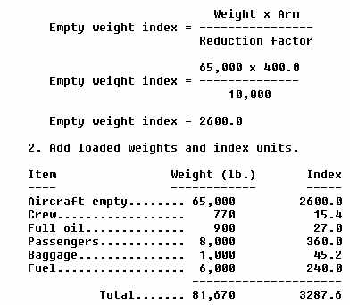 |
3. Divide the index by the weight:
3287.6
------ = 0.04025
81,670
4. To find c.g., move the decimal point to the right the same number
of places as there are zeros in the reduction factor:
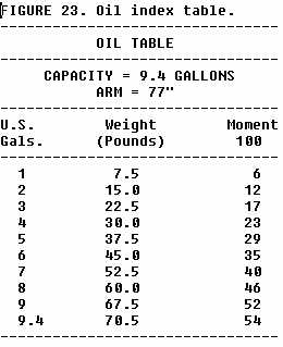
| The index units given for the particular items in the problem above
are easily obtained from tables in the weight and balance reports for the
aircraft. Tables are provided for all types of items which may be loaded
on the aircraft. A typical table is shown in figure 23.
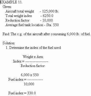
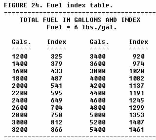
Index units may be used during flight to calculate the effect of fuel consumption upon the c.g. of the aircraft. The index units for the fuel used are subtracted from the aircraft total index which is calculated for takeoff conditions. The new c.g. is then obtained by dividing the new total index by the new total aircraft weight after fuel burnoff. Fuel consumption index units may either be obtained from a table, such as that shown in figure 24, or by calculations using weight, arm, and reduction factors. |
 |
 |
|
 |
 |
EXAMPLE 12.
Given:
Aircraft total weight - 101,000 lb.
c.g. - 20.0% MAC
MAC - Sta. 395 to Sta. 565
Reduction factor - 10.000
Find: What is the location of the c.g. in % MAC after consuming 4,000
gallons of fuel? Use the fuel index table (fig. 24):
Solution:
1. Determine original c.g. in inches from datum:
c.g. = LEMAC + (MAC x %)
c.g. = 395.0 + (170.0 in. x 0.20)
c.g. = 395.0 + 34.0 = 429.0 in.
2. Determine total weight index:
Weight x Arm
Total weight index = ----------------
Reduction factor
101,000 x 429.0
Total weight index = ---------------
10,000
Total weight index = 4332.9
3. Find fuel burned index on table (fig. 24):
Fuel burned index for 4,000 gals. = 1082.0
4. Convert fuel gallons to pounds: 4,000 gal. x 6.0 lb./gal. = 24,000 lb.
5. Subtract fuel burned weight and index from original total weight
and index:
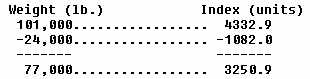 |
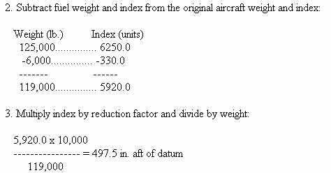
6. Multiply index by reduction factor and divide by weight:
3250.9 x 10,000
--------------- = 422.2 in. c.g. aft of datum
77,000
7. Determine c.g. in % MAC:
c.g. - LEMAC
------------ = % MAC
MAC
422.2 - 395.0
------------- = 16% MAC
170
CENTER OF GRAVITY VARIABLE LIMIT GRAPH
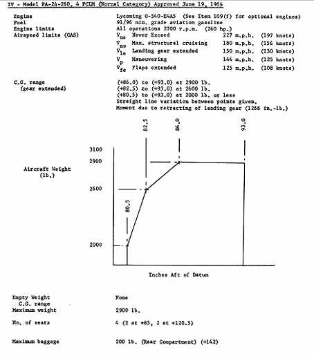
Many aircraft are designed with c.g. limits which vary with changes of weight and certain other operational factors. The limits are presented in the aircraft type certificate data sheets (fig. 19) or specifications and other publications in a graphic form and are usually expressed in inches from datum or % MAC. A typical graphic presentation of aircraft c.g. limits is shown in figure 25.
It is apparent from inspection of the graph that limits for various weights would include:
Weight Forward Aft
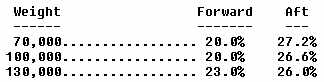 |
Limits for intermediate weights may be determined by visual or mathematical interpolation of the graph. The graph should be read to the nearest one-tenth of a percent of MAC. As an example, the rear limit for a weight of 90,000 lb. is interpolated to be 26.8% MAC.
The limits may be converted to "inches from datum" by computation methods previously explained. A typical problem using the limits in the graph (fig. 25) follows:
EXAMPLE 13.
Given:
Graphic c.g. limits (fig.
25)
MAC Sta. 400 to Sta. 560
Find: Forward c.g. limit for 115,000 lb. in inches from datum.
Solution:
1. Determine forward c.g. limit in % MAC by use of graph for 115,000 lb.:
Fwd. c.g. limit = 21.5% (.215)
2. Find length of MAC:
560 - 400 = 160 in.
3. Find limit in "inches from datum":
160 x 0.215 = 34.4 in. aft
of LEMAC
400 + 34.4 =
434.4 in. aft of datum
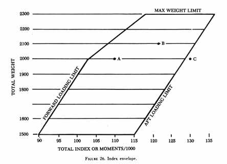
INDEX ENVELOPE
C.G. limits may be expressed graphically in the aircraft weight and balance reports by means of an index envelope. The envelope defines the forward and aft limits and also the maximum weight limit in terms of index units.
The envelope permits the rapid determination of the weight and balance condition of an aircraft when the weight and total index units are known. Thus, the procedure of computing the c.g. location from datum or in relation to MAC is simplified. The envelope informs the pilot that the c.g. is within acceptable limits without actually locating it on the longitudinal axis. In most cases, this is all the pilot needs to know. The pilot needs only to be assured that the c.g. is within approved limits.
A typical index envelope is shown in figure 26. The similarities and differences between this graphic form and the variable limit graph (fig. 25) should be noted.
It is apparent from the envelope that a loading of 2,000 lb. with an index of 110 is within limits (point A) while a loading of 2,000 lb. with an index of 130 is not within limits (point C). Index information which the operator must gather in order to utilize the envelope is obtained from index charts or tables in the weight and balance report. Various load items and associated index numbers are added to obtain the totals.
The following is a simplified loading check making use of the index
envelope:
 |
The intersection of the above total weight and total index values falls well within the index envelope (point B), therefore, the airplane in the example is considered to be within its operating limitations as far as weight and balance is concerned.
The index number system can be modified by applying selected constant
factors to the moments of load items. The selected constants are chosen
to make the index system less complex, and so that the system can be used
in conjunction with special loading charts. In these cases, special formulas
are used to obtain index units. Typical formulas are:
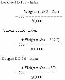 |
It should be noted that these special formulas are refinements of the standard formula:
Weight x Arm
Index = ----------------
Reduction factor
The constants that are used in the special formulas do not affect the
accuracy in determining c.g. locations, as long as the same formula is
applied to all weights and arms. These modifications to the index formula
permit the index numbers to be related easily to other important numbers,
such as % MAC and stabilizer setting.