The principles of weight and balance which have been discussed in previous chapters apply to large aircraft used by the air carriers and commercial operators as well as to small aircraft used by general aviation pilots and operators. The general concept of weights, arms, and moments apply regardless of aircraft size. The location of the c.g. can always be found by dividing total moments by total weight.
Large aircraft have the same dangerous flight characteristics as small aircraft when weight and balance limits are exceeded. It is not safe to assume that a large aircraft, because of its apparent abundance of engine power and spacious passenger and cargo compartments, cannot be loaded in an adverse manner. Any aircraft can be overloaded or loaded out of balance if weight and balance control procedures are not followed.
Aircraft which have a large number of passenger seats potentially possess great flexibility of loading configurations. From a utilization standpoint, such flexibility is desirable; but unless due consideration is given to weight and balance control, such an aircraft may easily be loaded in a nose-heavy or tail-heavy condition.
Large aircraft, particularly those operated by air carriers, are flown and maintained by a large number of people. No one pilot or mechanic may be fully and personally familiar with the loading or weight and balance condition of a particular aircraft. A properly documented weight and balance control system which is understood by flight, maintenance, and dispatch personnel is necessary for safe and orderly flight operations.
Weight control has a direct relationship to the profit or loss made
by air carrier and commercial operator aircraft. When extra fuel is required
for long trips or to allow for delays, the payload (passengers, baggage,
cargo) must be proportionately reduced to prevent exceeding maximum weight
limits. When trips are short and the payload is high, there are frequent
changes of passenger and cargo load. Under these conditions, a quick, accurate
method must be available to keep account of the aircraft weight and balance
condition.
WEIGHT AND BALANCE CONTROL PROCEDURES
The operator should develop a method and procedure by which it can be shown that the aircraft is properly loaded and will not exceed authorized weight and balance limitations during operation. The large aircraft operator should also account for all probable loading conditions which may be experienced in service and devise a loading schedule which will provide satisfactory weight and balance control. Loading schedules may be applied to individual aircraft or to a complete fleet. When an operator utilizes several types or models of aircraft, the loading schedule should be identified with the type or model of aircraft for which it is designed.
CENTER OF GRAVITY TRAVEL DURING FLIGHT
The operator's flight manual should show procedures which fully account for the extreme variations in c.g. travel during flight caused by all or any combination of the following variables:
1. The movement of passengers and cabin attendants from their normal
seat position in the aircraft cabin to the lounge or lavatory.
2. Possible change in c.g. position due to landing gear retraction.
3. The effect of the c.g. travel during flight due to fuel used.
RECORDS
The operator's weight and balance system should include methods by which responsible personnel will maintain a complete, current, and continuous record of the weight and c.g. of each aircraft. Such records should reflect all alterations and changes affecting either the weight or balance of the aircraft, and will include a complete and current equipment list. When fleet weights are used, pertinent computations should also be available in individual aircraft files.
The operations specifications of each air carrier should also contain the procedures used to maintain control of weight and balance of all aircraft operated under the terms of the carrier's operating certificate. The procedures should assure that the aircraft, under all operating conditions, is loaded within the gross weight and c.g. limitations. They should include a reference to the procedures used for determining weight of passengers and crew, weight of baggage, periodic aircraft weighing, type of loading devices, and identification of the aircraft concerned.
WEIGHT AND BALANCE SYSTEMS
The large aircraft operator's weight and balance control system may be in any form that proves workable. Several systems have been devised and many variations of the required documents are in use. All the systems strive for a rapid method of determining if the aircraft's weight and balance is within the stated tolerances. The systems are more sophisticated than those used for general aviation aircraft, however, they are subject to some of the same errors. Simple arithmetic errors and errors in updating necessary records after equipment changes are common sources of trouble. The latest systems are designed to eliminate the human error factor while speeding up the process of getting weight and balance information to the pilot and others who are responsible.
Weight and balance control systems are primarily based upon information contained in official sources, such as the Airplane Flight Manual, Type Certificate Data Sheets, etc. Ultimately, all systems are designed to provide values for a load manifest which in turn shows that the weight and balance condition is within limits for the flight.
AIRPLANE FLIGHT MANUAL
The airplane flight manual may be found in several forms - variations of the manuals are the result of the slight differences in operations by the various aircraft operators. Some manuals contain all the essential weight and balance information together with flight performance information in one volume, others utilize a separate volume for loading information.
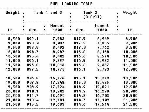
A typical manual contains an explanation of the approved weight and balance system. It also provides limitations as they apply to the aircraft under various operating conditions. Fuel loading charts are included, these charts indicate fuel load arrangements and also the moments or index which apply to a particular fuel load.
The loading section of the manual also contains information about passenger and cargo loading. It includes tabulated charts which indicate the index value for normal payloads. Instructions are also contained in the manual concerning procedures to use when the load is other than normal. For example, the manual explains the adjustments to make in passenger compartment index calculations when cargo containers are placed in passenger seats.
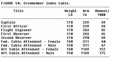
Typical information from the weight and balance section of the manual
is shown in the crewmember table, figure 50. It will be noted that the
table provides the normal weight and balance information (weight, arm,
and moment/1,000) which is to be used in the load manifest.
|
LOAD MANIFEST
The load manifest (fig. 51) is completed by use of information from the manual as it pertains to the particular flight. Basic operating weight is either calculated or carried forward from previous records. Payload and fuel load indexes are obtained from load tables. When the weight and index items are totaled on the load manifest, such factors as zero fuel weight, taxi gross weight, and c.g. in % MAC are indicated. The load manifest makes provisions for last minute corrections such as would be necessary when cargo or additional passengers are added just before takeoff. Weights on the load manifest may be indicated in kilograms (kilo or kg.), or pounds, or both. Forms used for international operations will usually have weights indicated in kilograms.
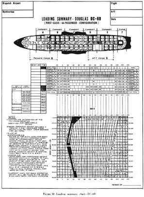
TYPICAL SYSTEMS
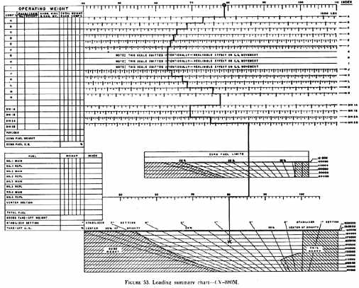
LOADING SUMMARY CHART. A typical approach to the problem of finding c.g. quickly is found in the use of a loading summary chart. Representative loading summary charts are shown in figures 52 and 53. These charts provide a means for determining c.g. position with some of the arithmetic steps omitted. Generally, the charts are entered at the top with basic operating weight and its index. Then a line is drawn downward and corrections are made to the right or left as appropriate for loads in each compartment. When all the compartment loads are considered, the line will indicate the zero fuel weight index. Continuing the line downward, a right or left adjustment is made for fuel load. The line is then terminated in the grid section of the chart at a horizontal line which represents the total weight. The terminal point of the line is an indication of c.g. in % MAC or index. Many turbojet aircraft load summary charts will provide an answer directly in stabilizer setting increments.
LOAD ADJUSTERS. Military aircraft have for many years made use of load adjusters for weight and balance computations. The load adjuster is a balance computer similar in form to the conventional slide rule. It consists of a base, a slide and a transparent, movable indicator. A representative load adjuster is illustrated in figure 54.
Load adjusters should never be interchanged between aircraft of different series or models. Although the method of using all load adjusters is generally the same, the scales that appear on a load adjuster are designed for use with one specific type of aircraft.
Generally, the load adjuster is used in a manner similar to the procedure explained for the load summary chart. The process begins with the basic operating weight and index. The index is always placed under the cursor or hairline of the load adjuster. Then the cursor is moved to the right or left a distance determined by the weight and index units for each load item added to the basic operating weight. As each load item is considered, the cursor is moved until all load items, including fuel have been accounted for. After the final movement of the cursor, the total weight index will appear under the cursor hairline.
The load adjuster also has a c.g. grid which permits quick conversion of the answer from total weight index to c.g. in % MAC. Inasmuch as the load adjuster is designed for one model airplane, the fore and aft limits are indicated on special scales. After determining total weight index, the location of the c.g. relative to its limits can easily be seen.
A diagram of the aircraft fuselage is normally included on the load adjuster. This diagram is used to help identify various compartment locations.
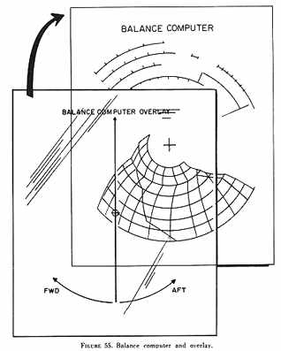
BALANCE COMPUTER. A slide rule can be circular as well as linear in construction - the aeronautical computer is an example of the circular type. Circular slide rules or computers have been adapted to the solution of weight and balance problems. Essentially, these balance computers are circular load adjusters, and like the linear type, can be used only for an aircraft of one make, model, and configuration. The identification markings of a balance computer should be carefully checked to insure its correct use.
The circular balance computer consists of a card and a curved c.g. grid. A different card is provided for each configuration aircraft and can be included in the weight and balance section of the aircraft flight manual. A transparent plastic overlay sheet with a simple straight line similar to the cursor on the load adjuster is used on top of the balance computer card (fig. 55).
The procedure for use of the circular balance computer is similar to that used on the slide rule type load adjuster. Starting with basic index units, progressive movements of the overlay are made in clockwise or counterclockwise directions. A pencil mark is made on the overlay before making each adjustment for a load item. After the final fuel item adjustment is accounted for, the line on the plastic overlay indicates the c.g. location where it crosses the gross weight line on the c.g. grid. The c.g. is indicated in % MAC on the grid and the grid itself is a limit envelope (fig. 55).
The design of the circular balance computer takes into account several general assumptions pertaining to the normal operation of the aircraft. Among these is the assumption that passengers will have a preference for empty seats next to the windows and that the fuel will be loaded and consumed according to standard schedules. If standard practices are followed, the computer allows omission of the intermediate steps of calculating moments and indexes for the load items.
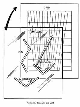
TEMPLATE AND GRID. A similar system makes use of a large weight and balance grid upon which the weight items are directly plotted. The grid indicates the weight and balance limits of the aircraft as expressed in % MAC. The grid can be printed on a hard plastic material from which the plot is erased after use or on a paper form which is kept as a record for each flight. The values for the load items are plotted progressively by the use of a plastic template (fig. 56). The final plot of the fuel load terminates at the intersection of the total weight and c.g. in % MAC.
As in all other systems, this system relies upon getting off to a good
start with a reliable basic operating weight and basic operating c.g. in
% MAC. Since the final plot represents the fuel load, the plotted fuel
line can be followed down the chart as fuel is consumed in flight to get
a continuous graphic indication of c.g. location during flight (fig.
57).
 |
ADVANCED SYSTEMS. New systems of weight and balance control are being devised and will undoubtedly be adopted in the future by the large aircraft operators. Electronic computers can be used to calculate and print out the weight and balance answers; the computer input possibly being based upon passenger and cargo reservation information.
Other systems have been investigated utilizing devices which measure the weight applied to each landing gear when the airplane is on the ground. These devices are installed in the landing gear system and produce a numerical readout of gross weight and c.g. position. The readout could be located in a convenient location in the flight compartment.
LARGE AIRCRAFT WEIGHT AND BALANCE RECORDS
It is apparent when a study is made of the weight and balance control systems introduced in this chapter, that the use of a valid Basic Operating Weight (BOW) is essential for accurate results. Operating personnel must rely upon BOW information in the aircraft records. Maintenance personnel must assure that the recorded BOW is correct.
BOW is defined as the weight of the aircraft as loaded ready for payload and fuel. The BOW, therefore, includes the empty aircraft with all permanently installed equipment, normal oil and fluids (except fuel), crew and crew baggage, passenger service equipment, emergency equipment, and special equipment.
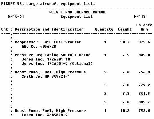
The aircraft is weighed to establish the empty weight and c.g. before it is put into service. When a record is made of this weighing, an equipment list is established which shows each item of installed equipment included in the empty weight. From then on, the condition for empty weight can be duplicated by assuring that this same equipment is installed. An excerpt from the equipment list of an FAA aircraft is shown in figure 58.
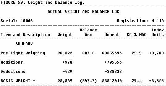
When equipment changes take place, an appropriate entry is made on a weight and balance log or the equipment list itself is amended so that the empty weight and c.g. are properly corrected. It is essential that any change in structure or equipment be entered in the records, otherwise all other calculations will be inaccurate. Part of a weight and balance log for an FAA aircraft is shown in figure 59.
The use of "empty fleet weights" and "basic operating fleet weights"
are explained in FAA Advisory Circular 120-27. When fleet weights are used,
weight and balance procedures can be standardized and periodic weighings
reduced; these advantages are possible when a large number of similar aircraft
are used by a particular operator.
 |
The term "zero fuel weight" indicates the maximum authorized weight of an aircraft without fuel - this weight is the sum of BOW and payload. It should be understood that passengers or cargo are included in zero fuel weight. When the zero fuel weight is high because of a large payload, the fuel load must be proportionately low to prevent exceeding maximum takeoff or landing weights. On the other hand, if a large fuel load is needed for a long range flight or for low altitude operation, IFR holding, or traffic delays, a reduction of payload and zero fuel weight may be required.
Average weights of adult passengers are assumed to be 160 pounds in summer (May 1 - Oct. 31) and 165 pounds in winter (Nov. 1 - Apr. 30). Children under 2 are considered "babes-in-arm" and children 2 through 12 are averaged at 80 pounds each. Passenger carry-on baggage is calculated at 5 pounds each. Most weight and balance control systems assume that passengers will select the window seats first, the aisle seats second, and the center of three abreast seating last. With these assumptions, passenger index tables are calculated. Allowances are made for those loading situations where passengers happen to group in extreme forward or aft locations. In flight, movement of passengers or crewmembers is also considered and load adjustments made. Any such allowances have the effect of reducing the load carrying flexibility of the aircraft.
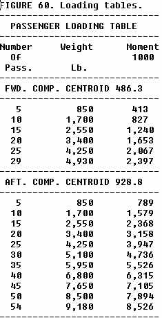
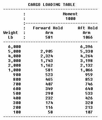
A typical passenger load index chart is shown in figure 60. It should be noted that this chart assumes that passengers are seated in the normal distribution around the center (centroid) of the forward and aft passenger compartments. A separate table in figure 60 provides information about cargo loads. The assumption is again made that the cargo is loaded evenly around the centroid of the cargo hold.
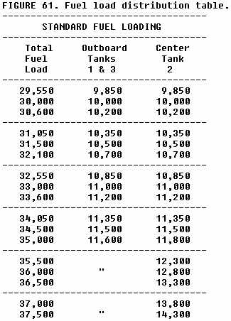
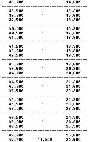
Fuel is loaded in large aircraft according to a schedule presented in
the FAA approved manuals. Such a procedure distributes the fuel among the
fuel tanks in a manner which will cause a minimum of difficulty with weight
and balance (fig. 61). Personnel involved with weight
and balance are, therefore, able to determine the fuel moments or index
from standard tables or by calculating the moment of the fuel in each tank.
Fuel is used according to procedures given in the flight manual. Besides
ensuring structural integrity, an important reason for following a standard
sequence of fuel tank selection is to control the c.g. location.
 |
|
 |
|
 |
 |
|
 |
|
The flight crew has a much less complex job in determining inflight c.g. travel if standard burnout procedures are followed.
When the aircraft is loaded ready for takeoff, the total weight of the aircraft is called taxi gross weight or ramp gross weight. Because of high fuel consumption during ground operation, this weight may be 500 to 1,000 pounds more than takeoff weight. Maximum takeoff weight is the maximum allowable just before brake release. This weight may be limited to a lesser weight for any particular takeoff by many factors related to aircraft performance. The actual takeoff weight limit is calculated by the use of various performance charts, taking into account such factors as: Runway length, temperature, density altitude, runway slope, and wind conditions.
Maximum landing weight is a structural limit and is the maximum weight authorized at touchdown. All weight in excess of maximum landing weight must consist of disposable fuel. A fuel dumping system is required on the aircraft if the maximum takeoff weight is more than 105 percent of maximum landing weight.
Conditions may arise during flight, such as engine failure or an aircraft system failure, which may require a landing sooner than originally planned. In this event, fuel may have to be dumped to reduce weight to maximum landing weight. If the fuel dumping procedures contained in the aircraft flight manual are followed, c.g. travel will remain within prescribed limits. Calculations of the effects of fuel dumping are similar to those used for fuel burn. Use of the fuel load table moments makes the calculations simple. Some manuals will provide a fuel tank centroid as a single arm, then the effect of fuel dumping can be calculated by a single remove weight formula such as the one which follows:
Weight before dumping - 160,000 lb.
c.g. before dumping - Sta. 615.5
Fuel to dump - 40,000 lb.
Centroid of fuel tanks - Sta. 750.2
Find c.g. after dumping.
Use remove weight formula:
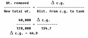 |
c.g. after dumping = 615.5 - 44.9 = 570.6 in.
STABILIZER TRIM SETTING
Before starting a takeoff in a large turbojet aircraft, the stabilizer trim must be placed in a position dictated by the c.g. location. An improperly set stabilizer trim may have such a powerful effect that it cannot be overcome by elevator control. During takeoff, it may be difficult to raise the nose (rotate at Vr); or on the other hand, the nose may pitch up uncontrollably depending on which direction the stabilizer is out of trim. Once the aircraft is airborne, the trim is adjusted by the pilot to a setting which will enable him to fly with minimum control pressure. The only acceptable procedure for takeoff is to set the trim according to c.g. location before the takeoff roll is started.
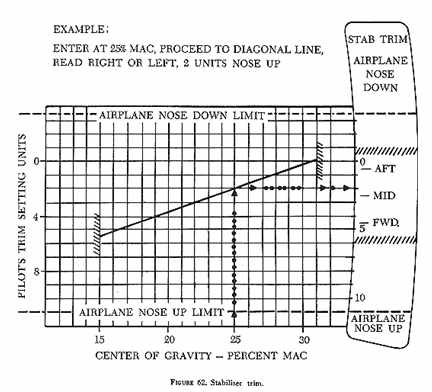
Some of the c.g. control systems previously explained (see Convair 880M loading summary, fig. 53) provide a stabilizer setting directly when the total weight c.g. is calculated. Other systems require the use of a simple chart to convert from c.g. in % MAC to stabilizer setting for a particular takeoff weight. A typical chart from an aircraft flight manual is illustrated in figure 62.
When the c.g. is determined to be located at a particular station, that location must first be converted to % MAC to use the stabilizer trim chart. A typical problem follows:
Given:
Takeoff c.g. - Sta. 575.0
MAC - Sta. 540.0 to Sta. 745.0
Stabilizer trim chart (fig. 62)
Find: Stabilizer trim setting for takeoff
Solution:
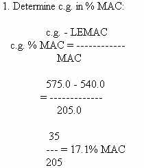
2. Determine stabilizer setting to nearest 1/2 unit:
Enter chart at bottom on 17.1% line.
Proceed upward to diagonal line.
Read stabilizer setting = 5 nose up.
LARGE AIRCRAFT LOADING PROBLEM
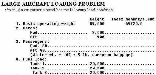 |
|
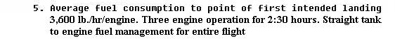 |
|
 |
|
 |
|
| Use loading tables -
figure
60
Use stabilizer trim setting chart - figure 62. |
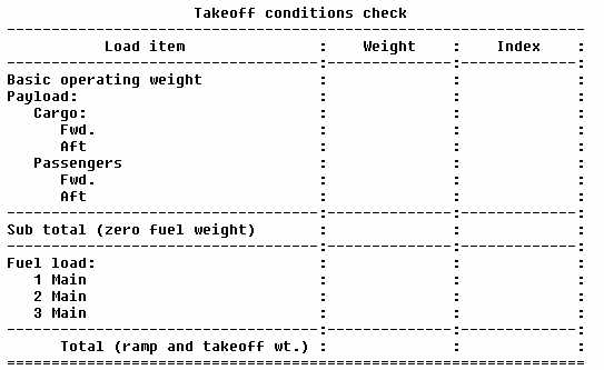 |
|
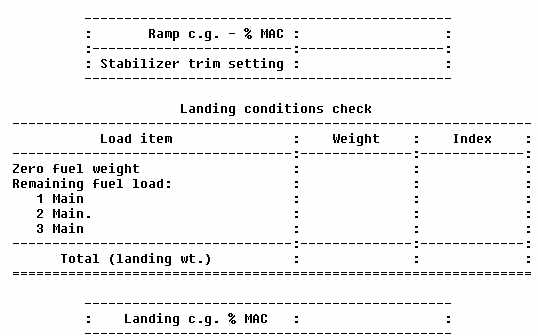 |
Notice that the fuel arms (fig. 60) vary with weight because the aircraft used in the problem is a swept wing type. The correct procedure is to add a new fuel index to the ZFW index. Subtraction of index units for fuel burned will not properly account for the change in arm.
Using the principles explained in the preceding chapters, you should be able to solve the sample problem. As a spot check, here are several answers:
1. No limits are exceeded.
2. Stabilizer trim for takeoff is one-half nose up.
3. C.G. at landing weight is 22.2% MAC.