FATIGUE EVALUATION
OF ROTORCRAFT STRUCTURE
| INTRODUCTION
BACKGROUND.
The fatigue evaluation procedures outlined in this advisory circular
are for guidance purposes only and are not mandatory nor regulatory in
nature. Although a uniform approach to fatigue evaluation is desirable,
it is recognized that in such a complex problem, new design features and
methods of fabrication, new approaches to fatigue evaluation, and new configurations
may require variations and deviations from the procedures described herein.
Engineering judgment should therefore be exercised for each particular
application.
a. The flight structure of the rotorcraft is subject to vibratory stresses
in practically every regime of flight. In addition, since it is a highly
maneuverable aircraft that is capable of forward, rearward, sideward, vertical,
and rotational flight, operating limitations due to fatigue are possible
in practically all flight situations. For these reasons, it is required
that special attention be focused on the fatigue evaluation of the flight
structure of the rotorcraft. |

|
b. Fatigue evaluation of the flight structure is intended to verify
structural reliability. Assurance of structural reliability starts with
design, including choice of materials for resistance to crack initiation
and/or propagation, detail design to minimize stress concentration, and
specification of surface finishes, fits, etc. Design analysis should include
estimation of expected flight loads, and estimation of resistance to fatigue.
Fatigue strength should be based on past full scale fatigue tests and/or
materials fatigue data with appropriate reductions for the variability
in fatigue strength, size, shape, surface finish, and environments of the
structure. In addition, design for fatigue should consider mode-of-failure
analysis, areas susceptible to fatigue cracking, and methods to assure
detectability of fatigue cracks. The residual strength of a cracked structure
is an important consideration of failsafe design.
c. Assurance of structural reliability also includes manufacture and
fabrication in accordance with design requirements and specifications,
quality control to monitor compliance, and effective service inspection
procedures.
d. Fatigue evaluation of the structure, measurement of flight loads
and stresses, and evaluation of fatigue strength and/or fatigue crack propagation
are the subjects of this advisory circular. There is some question whether
a completely reliable method for the prediction of time to fatigue crack
initiation and fracture exists. Nevertheless, one engineering approach
to the subject is to use the "Linear Cumulative Damage Hypothesis." This
hypothesis states that every cycle of stress above an "endurance limit"
produces fatigue damage proportional to the ratio of cycles accumulated
at the stress to fatigue "life" at that stress.
e. Laboratory tests of this hypothesis indicate that it is reasonably
valid when the loading spectrum consists of stresses which are, in effect,
random. Despite the lack of an adequate theory connecting this hypothesis
with more basic properties of materials, it has been successfully used
in a number of applications.
f. In addition, fatigue evaluation generally requires a method of accounting
for the effect of steady loads and stresses on fatigue. Where the manufacturer
does not provide other substantiating data, a Goodman diagram may be used
to account for these effects.
g. In any rational fatigue evaluation, the following factors should
be considered:
(1) Identification of the structure to be considered in the fatigue
evaluation.
(2) The stresses associated with steady and maneuvering operating conditions
expected in service.
(3) The frequency of occurrences associated with various flight conditions
and the corresponding spectrum of loadings and stresses.
(4) The fatigue strength, fatigue crack propagation characteristics
of the structure, and the residual strength of the cracked structure.
FLIGHT STRAIN MEASUREMENT PROGRAM
GENERAL.
Subsequent to design analysis, in which aircraft loads and associated
stresses are derived, the stress level and/or loads are to be verified
by a carefully controlled flight strain measurement program.
INSTRUMENTATION.
a. The instrumentation system used in the flight strain measurement
program should accurately measure and record the critical strains under
test conditions associated with normal operation and specific maneuvers.
The location and distribution of the strain gauges should be based on a
rational evaluation of the critical stress areas. This may be accomplished
by appropriate analytical means, supplemented, when deemed necessary, by
strain sensitive coatings or photoelastic methods. The distribution and
number of strain gauges must define the load spectrum adequately for each
part essential to the safe operation of the rotorcraft.
b. The corresponding flight parameters (airspeed, rotor rpm, center
of gravity accelerations, etc.) should also be recorded simultaneously
by appropriate methods. This is necessary in order to correlate the loads
and stresses with the maneuver or operating condition at which they occurred.
c. The instrumentation system should be adequately calibrated and checked
periodically throughout the flight strain measurement program in order
to ensure consistent and accurate results.
PARTS TO BE STRAIN GAUGED.
Fatigue critical portions of the rotor systems, control systems, fuselage,
and supporting structure for rotors, transmission, and engine are to be
strain gauged. For rotorcraft of unusual or unique design, special consideration
might be necessary to insure that all of the essential parts are evaluated.
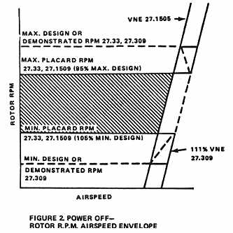
FLIGHT REGIMES AND CONDITIONS TO BE INVESTIGATED.
a. Typical flight and ground conditions to be investigated in the flight
strain measurement program are given in Table 1. Flight
regimes that should be investigated for power-on and power-off operation
are shown in Figures 1 and 2. For
clarity, the parameters which define these regimes are included in these
figures. As noted on Figure 1, complete coverage at
111 percent Vne should be demonstrated for power-on operation. However,
for power-off operation, Figure 2, complete coverage
at 111 percent Vne for maximum and minimum design rpm need not be obtained
if points are obtained at Vne at both maximum and minimum design rpm and
at 111 percent Vne at both maximum and minimum placarded rpm as indicated
in the figure.
b. The determination of flight conditions to be investigated in the
flight strain measurement program should be based on the anticipated use
of the helicopter, and, if available, on past service records for similar
designs. In any event, the flight conditions considered appropriate for
the design and application should be representative of the actual operation
in accordance with the rotorcraft flight manual. In the case of multiengine
helicopters, the flight conditions concerning partial engine-out operation
should be considered in addition to complete power-off operation. The flight
conditions to be investigated should be submitted in connection with the
flight evaluation program. Suggested flight conditions for single engine
helicopters used in normal operation are shown in Table
1.
c. The severity of the maneuvers investigated during the flight strain
survey should be such that it is unlikely that service use will be more
severe.
d. All flight conditions considered appropriate for the particular design
are to be investigated over the complete rotor speed, airspeed, center
of gravity, altitude, and weight ranges in order to determine the most
critical stress levels associated with each flight condition. In order
to account for data scatter and to determine the stress levels present,
a sufficient amount of data points should be obtained at each flight condition.
In some instances, the critical weight, center of gravity, and altitude
ranges for the various maneuvers can be based on past experience with similar
designs. This procedure is acceptable where adequate flight tests are performed
to substantiate such selections. The combinations of flight parameters
that produce the most critical stress levels should be included in the
fatigue evaluation.
FREQUENCY OF LOADING
TYPE OF OPERATION.
The probable types of operation (transport, utility, etc.) for the rotorcraft
should be established. The type of operation can have a major influence
on the loading environment. Normally, the rotorcraft should be substantiated
for the most critical general type of operation with consideration of special
occasional types of operation.
LOADING SPECTRUM.
The spectrum allocating percentages of time or frequencies of occurrence
to flight conditions or maneuvers is to be based on the expected usage
of the rotorcraft. This spectrum is to be such that it is unlikely that
actual usage will subject the structure to damage beyond that associated
with the spectrum. Considerations to be included in developing this spectrum
should include prior knowledge based on flight history recorder data, design
limitations established in compliance with FARs 27.309 or 29.309 and recommended
operating conditions and limitations specified in the rotorcraft flight
manual. The distribution of times at various forward flight speeds should
reflect not only the relation of these speeds to Vne but also the recommended
operating conditions in the rotorcraft flight manual which govern Vc or
cruise speed. Where possible, it is desirable to conduct the flight strain
gauge program by simulating the usage as determined above, with continuous
recording of stresses and loads, thus obtaining directly the stress/load
spectra for structural elements. Table 1 contains typical percent of occurrences
for the various flight conditions for single engine piston helicopters
used in utility operations. This table should be used only as a guide and
should be modified as necessary for each particular rotorcraft.
FATIGUE STRENGTH EVALUATION
GENERAL.
Information to guide fatigue evaluation based on safelife considerations
leading to recommended replacement times is provided in this section. Although
there is a large quantity of information available on the fatigue strength
characteristics of material specimens, built-up specimens and parts, the
prediction of strength of parts of new designs based on this information
is less reliable than testing the actual part. Consequently, additional
conservatism should be used with this method. However, in many cases the
differences between past test specimens and the actual part (which involve
such factors as stress concentration, size, and fretting) cannot be accounted
for with a reasonable degree of accuracy. Therefore, it is usually necessary
that the structural components be subjected to repeated load tests using
information determined in the flight strain measurement program. Special
operational or functional characteristics which could affect the fatigue
strength should also be considered in the service life evaluation. Such
factors as high blade operating temperatures due to tip jets or turbine
exhaust impingement on the tail rotor should be considered as well as other
special operating conditions. In addition effects of special purpose use
such as hoist and sling operation spraying, surveying, etc., should be
considered if appropriate to the particular type. The fatigue strength
should be evaluated by either of the methods outlined below, but full scale
testing is considered more accurate,
ANALYTICAL METHOD.
It is recognized that if allowable stress levels are established by
acceptable means, and the stresses measured in flight are lower than these
established levels, no fatigue testing is necessary.
a. Simplified method. The following techniques based on the use of the
Goodman diagram, are considered acceptable for establishing this allowable
stress level:
(1) Estimate the mean endurance limit of the part from test results
of specimens with similar stress concentrations. The test specimen material
should be representative of the actual part and sufficient test data should
be available to substantiate the mean endurance limit. The estimate should
account for surface conditions, fabrication methods, fretting, size and
shape effects, as well as differences in stress concentrations between
the test specimen and the actual part. Referring to Figure 3, the mean
endurance limit may be represented by a straight line drawn through the
yield stress (point A on the horizontal axis) and the maximum oscillatory
stress which the average specimen can withstand at a given steady stress
(Point B) without failure for 10^7 to 5 x 10^7 cycles depending on the
material.
(2) A factor of safety of 3 should then be applied to the mean endurance
limit so that the slope of line AC would be 1/3 of line AB. A smaller factor
is acceptable when substantiated by a sufficient number of tests on similar
parts in similar applications.
(3) If the flight strain measurements indicate that all of operating
stresses fall below the operating boundary line (AC), no fatigue testing
is necessary. When the measured stresses are above the operating boundary
line, however, fatigue testing of the actual parts should be conducted.
(4) Caution should be exercised in the application of the analytical
method above, particularly when the following items are involved:
(a) Large parts in proportion to the laboratory specimens.
(b) Irregularly shaped parts containing numerous or superimposed fillets,
holes, threads, or lugs.
(c) Parts of unique design for which no past service experience is
available.
(d) Parts subject to fretting.
(e) Bolted or pinned connections.
b. Rational methods. Methods may be used which do not involve full scale
testing but which apply the variables of fatigue strength with a calculation
of retirement times in a manner that provides equivalent reliability to
the fatigue testing and simplified methods and is acceptable to the Administrator.
TESTING METHODS.
The fatigue strength of the flight structure may be determined in appropriate
laboratory tests and evaluated in terms of a loading spectrum. The strength
indicated by the test results should be reduced by a factor such that a
replacement time based directly on this reduced strength level and the
loading spectrum of paragraph 7 will assure that the probability of failure
is extremely remote. This reduction factor should be based on consideration
of the number of specimens tested, the variability of the fatigue results,
the effects of service use, and, where available, previous test data for
the same material or similar components as well as service experience.
The test methods outlined below are considered acceptable.
a. S-N Curves.
(1) Fatigue tests should be conducted over a range of oscillatory stresses
or loads to define the S-N curves. Fatigue tests should be performed at
steady stresses or loads representative of those occurring in flight.
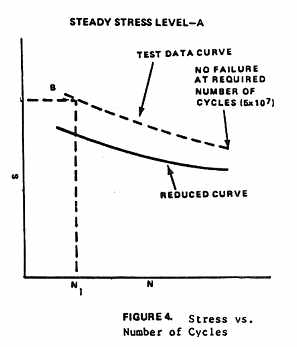
(2) In order to determine the mean fatigue strength and the variability
in fatigue strength, it is necessary to test a number of specimens in establishing
S-N curves. In order to account for the variability in fatigue strength,
a reduction factor should be applied to the mean curve in arriving at a
working S-N curve. This factor should include consideration of the number
of specimens tested, the variability of the fatigue results, and, where
available, previous test data on the same material or similar components,
as well as service experience. Where new materials or designs are being
evaluated, it is recommended that a larger reduction factor be used until
such time as additional test data justifying a change are available. The
mean and reduced S-N curve should reflect the curve shapes of typical published
S-N data on notched or unnotched specimens, as applicable. The reduced
S-N curve and the loading spectrum of paragraph 7 should be used in determining
replacement times. Figure 4 represents the method of
constructing a typical S-N curve from the fatigue test data.
b. Spectrum tests. The establishment of replacement times based on fatigue
tests in which each specimen is subjected to a spectrum of loading is to
include the following considerations:
(1) Definition of the test loading spectra based on either:
(a) Analysis, supported by extrapolation of available load history data
or prior knowledge where available, or
(b) Stress histories based on flight test data obtained for flight and
ground conditions and maneuvers considered appropriate for the particular
rotorcraft, and a spectrum allocating percentages of time or frequencies
of occurrence to these flight and ground conditions and maneuvers.
(2) Fatigue tests in which the loading spectra are applied such that
effective randomization of loadings is obtained.
(3) Unless performed prior to step (1), determining by flight test the
stress levels associated with each flight condition and maneuver considered
appropriate for the particular rotorcraft.
(4) Assignment of replacement times. The fatigue test results should
be evaluated in terms of the loading spectrum of paragraph 7 (if different
than test spectrum) and reduced by a factor considering the number of specimens,
the fatigue strength variability, and applicable prior data, in arriving
at a replacement time.
c. Major system tests. Another method of determining the replacement
times is to perform a fatigue test or tests of the major systems. Examples
of such testing are whirl tests, tiedown tests, and bench tests. The test
results should be evaluated in terms of the loading spectrum of paragraph
7 (if different from test loading) and reduced by a factor considering
number of specimens tested, variability in results, and applicable prior
test data in arriving at a replacement time.
COMBINATION OF REPLACEMENT TIME AND FAILSAFE EVALUATION.
It may be possible to extend the replacement time of safelife components
which exhibit limited failsafe capability by using a combination of the
safelife and failsafe concepts. This is accomplished by evaluating both
the fatigue strength and failsafe characteristics as described elsewhere
in this circular and by assigning both a replacement time and inspection
period to these components. The replacement time may then be based on the
combined probability of not initiating a fatigue crack at or before the
replacement time and the probability that the crack if initiated will be
detected prior to catastrophic failure or loss of limit load (or maximum
attainable load, whichever is less) carrying capability. The probability
of detection should be based on consideration of the inspection effectiveness,
the inspection interval, and the fatigue life remaining after an obvious
partial failure. A lower strength reduction factor, commensurate with this
probability of detection, may then be used in the determination of the
replacement time.
EXTENSION OF REPLACEMENT TIME.
Parts should be replaced or retired at the established service period
unless additional data indicate that an extension of the service period
is justified. Important factors in the consideration of such extension
would be:
a. Recorded load data. Recording load data entails instrumenting aircraft
in service to obtain a representative sampling of actual loads experienced.
The data measured should include airspeed, altitude, and rotor speed versus
time, or the airspeed, altitude, and strain ranges versus time, or similar
data. The data obtained by instrumenting aircraft in service should provide
a basis for correlating the estimated loading spectrum with the actual
service experience.
b. Additional analyses and tests. If test data and analyses based on
repeated load tests of additional specimens are obtained, a re-evaluation
of the initial strength reduction or scatter factor may be made.
c. Tests of parts removed from service. Where conservatism was used
in initial calculation of replacement times because of lack of knowledge
of service environment, repeated tests of replaced parts may be utilized
to re-evaluate the initial scatter factor selected. The tests should closely
simulate service loading conditions.
d. Rework of the structure. In some cases, rework of the structure may
result in an increase in replacement time.
FAILSAFE STRENGTH EVALUATION
GENERAL.
The failsafe strength evaluation of the flight structure is intended
to insure that, should fatigue cracks initiate, the remaining structure
will withstand service loads without failure until the cracks are detected.
The failsafe evaluation generally encompasses establishing the components
which are failsafe, defining the loading conditions and extent of damage
for which the structure is to be designed, conducting structural tests
and analysis to substantiate that the design objective has been achieved,
and establishing inspection programs to assure detection of fatigue damage.
On components predominantly loaded by centrifugal force, care should be
taken in selecting limit load to assure that it is the maximum expected
in service. Design features which may be used in attaining a failsafe structure
are:
a. Selection of materials and stress levels that provide a controlled
slow rate of crack propagation combined with high residual strength after
initiation of cracks.
b. Design to permit detection of cracks including the use of crack detection
systems, in all critical structural elements before the cracks can become
dangerous or result in appreciable strength loss, and to permit replacement
or repair.
c. Use of multipath construction and the provision of crack stoppers
to limit the growth of cracks.
d. Use of composite duplicate structures so that a fatigue crack or
failure occurring in one element of the composite member will be confined
to that element and the remaining structure will still possess appreciable
load carrying ability.
e. Use of backup structure wherein one member carries all the load,
with a second member available and capable of assuming the extra load if
the primary member fails.
IDENTIFICATION OF CRITICAL PORTIONS OF FLIGHT STRUCTURE.
Those portions of the flight structure which may be critical in fatigue
should be identified,. Typical portions of the structure are:
a. Rotor blades and attachment fittings.
b. Rotor heads, including hubs, hinges, dampers.
c. Control system components, including control rods, servos, swashplates.
d. Rotor supporting structure.
e. Fuselage, including stabilizers and auxiliary lifting surfaces.
EXTENT OF FAILSAFE DAMAGE.
The extent of the partial failure is to be such that it would be readily
detectable during the specified inspection. It may involve complete failure
of a principal element, failure of more than one element, or only a partial
failure of an element depending on the rate of crack propagation, the ease
of detection, and the inspection interval. Damage in inaccessible areas
should extend into inspectable areas.
Typical examples of the fatigue damage which should be considered are
outlined below:
a. Cracks emanating from the edge of structural openings or cutouts
which can be readily detected by visual inspection of the area.
b. A circumferential or longitudinal skin crack in the basic fuselage
structure of such a length that it can be readily detected by a visual
inspection of the surface area.
c. Complete severance of interior frame elements or stiffeners in addition
to a visually detectable crack in the adjacent skin.
d. Failure of one element where dual construction is utilized in components.
e. Failure of primary attachments, including control hinges and fittings.
DETERMINATION OF PROBABLE CRACK LOCATIONS.
The probable crack locations are to be determined by tests, analysis,
or both. In cases of unusually critical or complex components or when initial
fatigue loadings may affect the rate or mode of cracking, the probable
crack locations should be determined by fatigue test. When determination
is made by analysis, sound engineering judgment should be used and a variety
of factors such as the following taken into account:
a. Conducting an analysis to locate areas of maximum stress and low
margin of safety.
b. Conducting strain surveys on undamaged structure to establish points
of high stress concentration as well as the magnitude of such concentration.
c. Examining static test results to determine locations where excessive
deformation occurred.
d. Determining from fatigue analysis where cracks may initiate.
e. Selecting locations in an element where the stresses in adjacent
elements would be the maximum with that element failed.
f. Selecting partial fracture locations in an element wherein high
stress concentrations are present in the residual structure,
g. Assessing design detail areas which are prone to fatigue damage
based on service experience records of similarly designed components.
FAILSAFE DEMONSTRATION.
It is to be demonstrated by analysis, tests, or both, that the structure
with the partial failures as defined in paragraphs 15 and 16 can withstand
the maximum load and the repeated loads expected in service during the
period prior to detection. The repeated loads should be as defined in the
loading spectrum of paragraph 7 and the structure should be capable of
supporting this loading after a partial failure for a sufficient time with
respect to the inspection interval to assure that catastrophic failure
is extremely remote. The loading spectrum should include at least one application
of limit load. In test demonstrations, the damage may be initiated or simulated
by cuts made with a fine saw, sharp blade, or guillotine in those cases
where it is not necessary and not practical to produce fatigue cracks by
tests. In those cases where damage is simulated at joints or fittings,
bolts may be removed to simulate failure if this condition would be representative
of an actual failure. In some instances, the failsafe characteristics may
be shown analytically. The analytical approach may be used when the structural
configuration involved is essentially similar to one already verified by
failsafe tests, whether on a previously approved type design, or on other
similar areas of the design currently being evaluated. The analytical approach
may also be used when: (1) it can be shown that the failure would be detected
considerably before the critical crack length is approached; (2) the margins
of safety resulting from the analysis are well in excess of the failsafe
residual static strength level; and (3) the stress levels in the partially
failed structure and the design are such as to assure adequate crack propagation
time relative to the inspection interval.
INSPECTION.
Detection of fatigue cracks before they become dangerous is the ultimate
control in insuring the failsafe characteristics of the structure. Therefore,
the manufacturer should provide sufficient guidance information to assist
operators in establishing the frequency and extent of the repeated inspections
of the critical structure.