AvStop Magazine Online
![]()
From Nicholson's Journal, February, 1810
BY SIR GEORGE CAYLEY, BART.
|
HAVING, in my former communication, described the general principle of support in aerial navigation, I shall proceed to show how this principle must be applied, so as to be steady and manageable. Several persons have ventured to descend from balloons in what is termed a parachute, which exactly resembles a large umbrella, with a light car suspended by cords underneath it. Mr. Garnerin's descent in one of these machines will be in the recollection of many; and I make the remark for the purpose of alluding to the continued oscillation, or want of steadiness, which is said to have endangered that bold aeronaut. It is, very remarkable, that the only machines of this sort, which have been constructed, are nearly of the worst possible form for producing a steady descent, the purpose for which they are intended. To render this subject more familiar, let us recollect, that in a boat, swimming upon water, its stability or stiffness depends, in general terms, upon the weight and distance from the centre of the section elevated above the water, by any given heel of the boat, on one side; and on the bulk, and its distance from the centre, which is immersed below the water, on the other side; the combined endeavour of the one to fall, and of the other to swim, produces the desired effect in a well-constructed boat. The centre of gravity of the boat being more or less below the centre of suspension is an additional cause of its stability. |
 |
 |
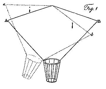
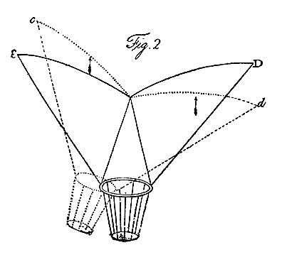
Let us now examine the effect of a parachute represented by A B, Fig. I, Pl. III. When it has heeled into the position a b, the side a is become perpendicular to the current, created by the descent, and therefore resists with its greatest power; whereas the side b is become more oblique, and of course its resistance is much diminished. In the instance here represented, the angle of the parachute itself is 144°, and it is supposed to heel 18°, the comparative resistance of the side a to the side b, will be as the square of the line a , as radius, to the square of the sine of the angle of b with the current; which, being 54 degrees, gives the resistances nearly in the ratio of 1 to 0.67; and this will be reduced to only 0.544, when estimated in a direction perpendicular to the horizon. Hence, so far as this form of the sail or plane is regarded, it operates directly in opposition to the principle of stability; for the side that is required to fall resists much more in its new position, and that which is required to rise resists much less; therefore complete inversion would be the consequence, if it were not for the weight being suspended so very much below the surface, which, counteracting this tendency, converts the effort into a violent oscillation. On the contrary, let the surface be applied in the inverted position, as represented at C D, Fig. 2, and suppose it to be heeled to the same angle as before, represented by the dotted lines c d. Here the exact reverse of the former instance takes place; for that side, which is required to rise, has gained resistance by its new position, and that which is required to sink has lost it; so that as much power operates to restore the equilibrium in this case, as tended to destroy it in the other: the operation very much resembling what takes place in the common boat.1 |
|
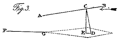
This angular form, with the apex downward, is the chief basis of stability in aerial navigation; but as the sheet which is to suspend the weight attached to it, in its horizontal path through the air, must present a slightly concave surface in a small angle with the current, this principle can only be used in the lateral extension of the sheet; and this most effectually prevents any rolling of the machine from side to side. Hence, the section of the inverted parachute, Fig. 2, may equally well represent the cross section of a sheet for aerial navigation. The principle of stability in the direction of the path of the machine, must be derived from a different source. Let A B, Fig. 3, be a longitudinal section of a sail, and let C be its centre of resistance, which experiment shows to be considerably more forward than the centre of the sail. Let C D be drawn perpendicular to A B, and let the centre of gravity of the machine be at any point in that line, as at D. Then, if it be projected in a horizontal path with velocity enough to support the weight, the machine will retain its relative position, like a bird in the act of skimming; for, drawing C E perpendicular to the horizon, and D E parallel to it, the line C E will, at some particular moment, represent the supporting power, and likewise its opponent the weight; and the line D E will represent the retarding power, and its equivalent, that portion of the projectile force expended in overcoming it: hence, these various powers being exactly balanced, there is no tendency in the machine but to proceed in its path, with its remaining portion of projectile force. |
 |
 |
The stability in this position, arising from the centre of gravity being below the point of suspension, is aided by a remarkable circumstance, that experiment alone could point out. In very acute angles with the current it appears, that the centre of resistance in the sail does not coincide with the centre of its surface, but is considerably in front of it. As the obliquity of the current decreases, these centres approach, and coincide when the current becomes perpendicular to the sail. Hence any heel of the machine backward or forward removes the centre of support behind or before the point of suspension; and operates to restore the original position, by a power, equal to the whole weight of the machine, acting upon a lever equal in length to the distance the centre has removed. To render the machine perfectly steady, and likewise to enable it to ascend and descend in its path, it becomes necessary to add a rudder in a similar position to the tail in birds. Let F G be the section of such a surface, parallel to the current; and let it be capable of moving up and down upon G, as a centre, and of being fixed in any position. |
The powers of the machine being previously balanced, if the least pressure be exerted by the current, either upon the upper or under surface of the rudder, according to the will of the aeronaut, it will cause the machine to rise or fall in its path, so long as the projectile or propelling force is continued with sufficient energy. From a variety of experiments upon this subject I find, that, when the machine is going forward with a superabundant velocity, or that which would induce it to rise in its path, a very steady horizontal course is effected by a considerable depression of the rudder, which has the advantage of making use of this portion of sail in aiding the support of the weight. When the velocity is becoming less, as in the act of alighting, then the rudder must gradually recede from this position, and even become elevated, for the purpose of preventing the machine from sinking too much in front, owing to the combined effect of the want of projectile force sufficient to sustain the centre of gravity in its usual position, and of the centre of support approaching the centre of the sail.
The elevation and depression of the machine are not the only purposes, for which the rudder is designed. This appendage must be furnished with a vertical sail, and be capable of turning from side to side, in addition to its other movements, which effects the complete steerage of the vessel. All these principles, upon which the support, steadiness, elevation, depression, and steerage, of vessels for aerial navigation, depend, have been abundantly verified by experiments both upon a small and a large scale. Last year I made a machine, having a surface of 300 square feet, which was accidentally broken before there was an opportunity of trying the effect of the propelling apparatus; but its steerage and steadiness were perfectly proved, and it would sail obliquely downward in any direction, according to the set of the rudder. Even in this state, when any person ran forward in it, with his full speed, taking advantage of a gentle breeze in front, it would bear upward so strongly as scarcely to allow him to touch the ground; and would frequently lift him up, and convey him several yards together.
The best mode of producing the propelling power is the only thing, that remains yet untried toward the completion of the invention. I am preparing to resume my experiments upon this subject, and state the following observations, in the hope that others may be induced to give their attention towards expediting the attainment of this art. The act of flying is continually exhibited to our view; and the principles upon which it is effected are the same as those before stated. If an attentive observer examines the waft of a wing, he will perceive, that about one third part, toward the extreme point, is turned obliquely backward; this being the only portion, that has velocity enough to overtake the current, passing so rapidly beneath it, when in this unfavourable position. Hence this is the only portion that gives any propelling force .
To make this more intelligible, let A B, Fig. 4, be a section of this part of the wing. Let C D represent the velocity of the bird's path, or the current, and E D that of the wing in its waft: then C E will represent the magnitude and direction of the compound or actual current striking the under surface of the wing. Suppose E F, perpendicular to A B, to represent the whole pressure; E G being parallel to the horizon, will represent the propelling force; and G F, perpendicular to it, the supporting power. A bird is supported as effectually during the return as during the beat of its wing; this is chiefly effected by receiving the resistance of the current under that portion of the wing next the body where its receding motion is so slow as to be of scarcely any effect. The extreme portion of the wing, owing to its velocity, receives a pressure downward and obliquely forward, which forms a part of the propelling force; and at the same time, by forcing the hinder part of the middle portion of the wing downward, so increases its angle with the current, as to enable it still to receive nearly its usual pressure from beneath.
As the common rook has its surface and weight in the ratio of a square foot to a pound, it may be considered as a standard for calculations of this sort; and I shall therefore state, from the average of many careful observations, the movements of that bird. Its velocity, represented by C D, Fig. 4, is 34.5 feet per second. It moves its wing up and down once in flying over a space of 12.9 feet. Hence, as the centre of resistance of the extreme portion of the wing moves over a space of 0.75 of a foot each beat or return, its velocity is about 4 feet per second, represented by the line E D. As the wing certainly overtakes the current, it must be inclined from it in an angle something less than 7°, for at this angle it would scarcely be able to keep parallel with it, unless the waft downward were performed with more velocity than the return; which may be and probably is the case, though these movements appear to be of equal duration. The propelling power, represented by E G, under these circumstances, cannot be equal to an eighth part of the supporting power G F, exerted upon this portion of the wing; yet this, together with the aid from the return of the wing, has to overcome all the retarding power of the surface, and the direct resistance occasioned by the bulk of the body.
It has been before suggested, and I believe upon good grounds, that very acute angles vary little in the degree of resistance they make under a similar velocity of current. Hence it is probable, that this propelling part of the wing receives little more than its common proportion of resistance, during the waft downward. If it be taken at one-third of the whole surface, and one-eighth of this be allowed as the propelling power, it will only amount to one twenty fourth of the weight of the bird; and even this is exerted only half the duration of the flight. The power gained in the return of the wing must be added, to render this statement correct, and it is difficult to estimate this; yet the following statement proves, that a greater degree of propelling force is obtained, upon the whole, than the foregoing observations will justify. Suppose the largest circle that can be described in the breast of a crow, to be 12 inches in area. Such a surface, moving at the velocity of 34.5 feet per second, would meet a resistance of 0.216 of a pound, which, reduced by the proportion of the resistance of a sphere to its great circle (given by Mr. Robins as 1 to 2.27) leaves a resistance of 0.095 of a pound, had the breast been hemispherical. It is probable however, that the curve made use of by Nature to avoid resistance, being so exquisitely adapted to its purpose, will reduce this quantity to one half less than the resistance of the sphere, which would ultimately leave 0.0475 of a pound as somewhat approaching the true resistance. Unless therefore the return of the wing gives a greater degree of propelling force than the beat, which is improbable, no such resistance of the body could be sustained. Hence, though the eye cannot perceive any distinction between the velocities of the beat and return of the wing, it probably exists, and experiment alone can determine the proper ratios between them.
From these observations we may, however, be justified in the remark -- that the act of flying, when properly adjusted by the Supreme Author of every power, requires less exertions than, from the appearance, is supposed.
1 A very simple experiment will show the truth of this theory. Take a circular piece of writing paper, and folding up a small portion, in the line of two radii, it will be formed into an obtuse cone. Place a small weight in the apex, and letting it fall from any height, it will steadily preserve that position to the ground. Invert it, and, if the weight be fixed, like the life boat, it rights itself instantly.