![]()
![]()
|
|
|
|
Chapter 1. Structural Data
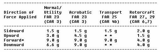
a. Limit Load Factors are the maximum load factors which may be expected during service (the maneuvering, gust, or ground load factors established by the manufacturer for type certification). b. Ultimate Load Factors are the limit load factors multiplied by a prescribed factor of safety. Certain loads, such as the minimum ultimate inertia forces prescribed for emergency landing conditions, are given directly in terms of ultimate loads. c. Static Test Load Factors are the ultimate load factors multiplied by prescribed casting, fitting, bearing, and/or other special factors. Where no special factors apply, the static test load factors are equal to the ultimate load factors. d. Critical Static Test Load Factors are the greater of the maneuvering, gust, ground, and inertia load static test load factors for each direction (up, down, side, fore, and aft). Static tests using the following load factors are acceptable for equipment
installations:
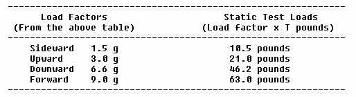
* When equipment mounting is located externally to one side, or forward of occupants, a forward load factor of 2.0 g is sufficient. ** Due to differences among various aircraft designs in flight and ground load factors, contact the aircraft manufacturer for the load factors required for a given model and location. In lieu of specific information, the factors used for FAR 23 utility category are acceptable for aircraft with never exceed speed of 250 knots or less and the factors used for FAR 23 acrobatic category for all other transport aircraft. The following is an example of determining the static test loads for
a 7 pound piece of equipment to be installed in a utility category aircraft
(FAR Part 23).
When an additional load is to be added to structure already supporting previously installed equipment, determine the capability of the structure to support the total load (previous load plus added load). 3. STATIC TESTS. Caution: The aircraft and/or equipment can be damaged in applying static loads, particularly if careless or improper procedure is used. It is recommended, whenever practicable, that static testing be conducted on a duplicate installation in a jig or mockup which simulates the related aircraft structure. Static test loads may exceed the yield limits of the assemblies being substantiated and can result in partially sheared fasteners, elongated holes, or other damage which may not be visible unless the structure is disassembled. If the structure is materially weakened during testing, it may fail at a later date. Riveted sheet metal and composite laminate construction methods especially do not lend themselves to easy detection of such damage. To conduct static tests: a. Determine the weight and center of gravity position of the equipment item. b. Make actual or simulated installation of attachment in the aircraft or preferably on a jig using the applicable static test load factors. c. Determine the critical ultimate load factors for the up, down, side, fore, and aft directions. A hypothetical example which follows steps (1) through (4) below is shown in figure 1.1. (1) Convert the gust, maneuvering, and ground load factors obtained from the manufacturer or FAA engineering to ultimate load factors. Unless otherwise specified in the airworthiness standards applicable to the aircraft, ultimate load factors are limit load factors multiplied by a 1.5 safety factor. (See columns 1, 2, and 3 for items A. B, and C of figure 1.1.) (2) Determine the ultimate inertia load forces for the emergency landing conditions as prescribed in the applicable airworthiness standards. (See items D and E, column 3. of figure 1.1..) (3) Determine what additional load factors are applicable to the specific seat, litter, berth, or cargo tiedown device installation. The ultimate load factors are then multiplied by these factors to obtain the static test factors. (To simplify this example, only the seat, litter, berth, and safety belt attachment factor of 1.33 was assumed to be applicable. See Item E, column 4, of figure 1.1.) (4) Select the highest static test load factors obtained in Steps 1, 2, and/or 3 for each direction (up, down, side, fore, and aft). These factors are the critical static test load factors used to compute the static test load. (See column 6 of figure 1.1.) d. Apply load at center of gravity position (of equipment item or dummy) by any suitable means that will demonstrate that the attachment and structure are capable of supporting the required loads. When no damage or permanent deformation occurs after 3 seconds of applied static load, the structure and attachments are acceptable. Should permanent deformation occur after 3 seconds, repair or replace the deformed structure to return it to its normal configuration and strength. Additional load testing is not necessary. 4. MATERIALS. Use materials conforming to an accepted standard such as AN, NAS, TSO, or MIL-SPEC. 5. FABRICATION. When a fabrication process which requires close control is used, employ methods which produce consistently sound structure that is compatible with the aircraft structure. 6. FASTENERS. Use hardware conforming to an accepted standard such as AN, NAS, TSO, or MIL-SPEC. Attach equipment so as to prevent loosening in service due to vibration. 7. PROTECTION AGAINST DETERIORATION. Provide protection against deterioration or loss of strength due to corrosion, abrasion, electrolytic action, or other causes. 8. PROVISIONS FOR INSPECTION. Provide adequate provisions to permit close examination of equipment or parts of the aircraft that regularly require inspection, adjustment, lubrication, etc. 9. EFFECTS ON WEIGHT AND BALANCE. Assure that the altered aircraft can be operated within the weight and center of gravity ranges listed in the FAA Type Certificate (TC) Data Sheet or Aircraft Listing. Determine that the altered aircraft will not exceed maximum gross weight. (If applicable, correct the loading schedule to reflect the current loading procedure. Consult Advisory Circular 43.13-1A, "Acceptable Methods, Techniques, and Practices - Aircraft, Inspection and Repair" for Weight and Balance Computation Procedures. 10. EFFECTS ON SAFE OPERATION. Install equipment in a manner that will not interfere with or adversely affect the safe operation of the aircraft (controls, navigation equipment operation, etc.). 11. CONTROLS AND INDICATORS. Locate and identify equipment controls and indicators so they can be operated and read from the appropriate crewmember position. 12. PLACARDING. Label equipment requiring identification and, if necessary, placard operational instructions. Amend weight and balance information as required. 13. - 20. [RESERVED] |
||||||
| ©AvStop Online Magazine Contact Us Return Home |