
![]()
![]()
|
|
|
|
Chapter 10. Battery Installations
a. Accessibility for Battery Maintenance and Removal.
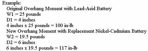
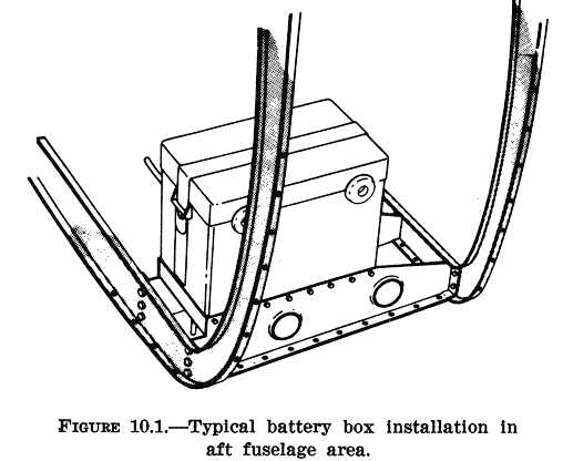
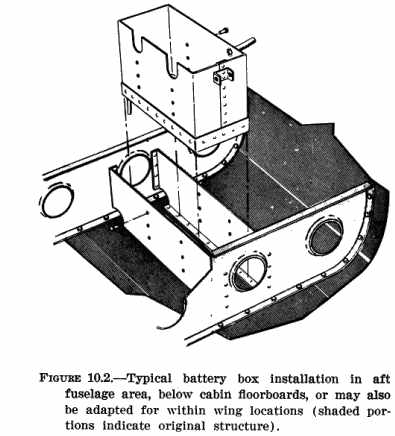
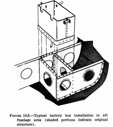
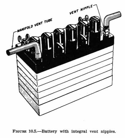
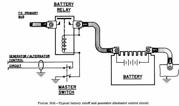
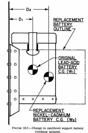
b. Protection from Engine Heat. The installation should protect the battery from extreme engine heat, which would be detrimental to the battery's service life and reliability. Such protection should provide for the temperatures encountered after engine shutdown as well as during engine operation. When locating the battery within the engine compartment, choose a location that will not interfere with the flow of engine cooling air. c. Protection from Mechanical Damage. Vibration and other shock loads are a major cause of short battery life. Whenever possible install the battery in a manner or location that will minimize damage from airframe vibration and prevent accidental damage by passengers or cargo. d. Passenger Protection. Enclose the battery in a box or other suitable structure to protect passengers from any fumes or electrolyte that may be spilled as a result of battery overheating, minor crash, inverted flight, and/or rapid decompression if the battery is located within the aircraft's pressure vessel. e. Airframe Protection. Protect the airframe structure and fluid lines by applying asphaltic or rubber-base paint to the areas adjacent to and below the battery or battery box. Apply paralketone, heavy grease, or other comparable protective coating to control cables in the vicinity of the battery or battery box. Damage to adjacent fabric covering and electrical equipment can be minimized by providing a battery sump jar containing a neutralizing agent, properly locating battery drains and vent discharge lines, and adequately venting the battery compartment. 178. DUPLICATION OF THE MANUFACTURER'S INSTALLATION. The availability of ready made parts and attachment fittings may make it desirable to consider the location and type of installation selected and designed by the airframe manufacturer. Appreciable savings in time and work may be realized if previously approved data and/or parts are used. 179. OTHER INSTALLATIONS. If the battery installation has not been previously approved, or if the battery is to be installed or relocated in a manner or location other than provided in previously approved data, perform static tests on the completed installation as outlined in chapter 1 of this handbook. Because of the concentrated mass of the battery, the support structure should also be rigid enough to prevent undue vibration which would lead to early structural failure. Typical illustrations of battery support structure are shown in figures 10.1 thru 10.4. {See Figure 10.2} {See Figure 10.3} 180. - 185. [RESERVED] Section 2. INSTALLATION 186. SECURING THE BATTERY. Install the battery box or hold-downs in such a manner as to hold the battery securely in place without subjecting it to excessive localized pressure which may distort or crack the battery case. Use rubber or wooden blocks protected with paraffin or asphaltic paint as spacers within the battery box, as necessary, to prevent shifting of the battery and possible shorting of the battery terminals or cables. Also, provide adequate clearance between the battery and any bolts and/or rivets which may protrude into the battery box or compartment. 187. VENTING. Provide suitable venting to the battery compartment to prevent the accumulation of the hydrogen gas evolved during operation. For most aircraft batteries, an airflow of 5 cubic feet per minute is sufficient to purge the battery compartment of explosive concentrations of hydrogen. a. Manifold Type. In this type of venting, one or more batteries are connected, via battery or battery box vent nipples, to a hose or tube manifold system as shown in figure 10.5. Fasten such hoses securely to prevent shifting and maintain adequate bend radii to prevent kinking. (1) The upstream side of the system is connected to a positive pressure point on the aircraft, and the downstream side is usually discharged overboard to a negative pressure area. It is advisable to install a battery sump jar in the downstream side to neutralize any corrosive vapors that may be discharged. (2) When selecting these pressure points, select points that will always provide the proper direction of airflow through the manifold system during all normal operating attitudes. Reversals of flow within the vent system should not be permitted when a battery sump jar is installed, as the neutralizing agent in the jar may contaminate the electrolyte within the battery. b. Free Airflow Type. Battery cases or boxes that contain louvers may be installed without an individual vent system, provided: (1) The compartment in which the battery is installed has sufficient airflow to prevent the accumulation of explosive mixtures of hydrogen; (2) Noxious fumes are directed away from occupants; and (3) Suitable precautions are taken to prevent corrosive battery fluids or vapors from damaging surrounding structure, covering, equipment, control cables, wiring, etc. 188. DRAINS. Position battery compartment drains so that they do not allow spillage to come in contact with the aircraft during either ground or flight attitudes. Route the drains so that they have a positive slope without traps. Drains should be at least 1/2" in diameter to prevent clogging. 189. ELECTRICAL INSTALLATION. a. Cables/Connectors. Use cables and/or connectors that are adequately rated for the current demand and are properly installed (See AC 43.13-1A, "Acceptable Methods, Techniques, and Practices - Aircraft Inspection and Repair," chapter 11). It may be necessary to contact the battery manufacturer to determine current value of the battery at the 5 minute discharge rate. Cable size can also be selected by using the same gauge as used on a previously approved production aircraft with the same battery. (1) The cables should be of sufficient length to prevent undue strain on the battery connector or terminals. (2) Clamp and protect cables, including the bus, in a very secure manner. Since these units are not fused, any fault could cause loss of the entire electrical system in addition to a possible fire hazard. (3) Route cables so that cable or terminals cannot short to the battery case or hold-down frame. (4) Route cables outside the battery box whenever practicable to prevent corrosion by acid fumes. When internal routing is unavoidable, protect the cable inside the box with acidproof tubing. Assure that cables will not be inadvertently reversed on the battery terminals either by proper cable lengths and clamps or, if this is not practicable, use conspicuous color coding. b. Battery Cutoff. Install a battery cutoff relay to provide a means of isolating the battery from the aircraft's electrical system. An acceptable battery cutoff circuit is shown in figure 10.6. Mount the relay so that the cable connecting the relay to the battery is as short as feasible, in any case not to exceed two feet, to reduce the possibility of a fire occurring because of a short within this section of cable. 190. - 195. [RESERVED] Section 3. REPLACEMENT OF LEAD-ACID BATTERIES WITH NICKEL-CADMIUM BATTERIES 196. GENERAL. Nickel-cadmium batteries fulfill a need for a power source that will provide large amounts of current, fast recharge capability, and a high degree of reliability. The exchange of lead-acid for nickel-cadmium batteries requires careful evaluation of certain areas. 197. ELECTRICAL ANALYSIS. The ampere hour capacity of a nickel-cadmium battery is selected to accommodate the aircraft load requirements. When making this selection, the following items should be considered. a. The low internal resistance permits it to recharge very quickly. This high recharge rate can exceed the generator rated capacity and deprive essential circuits of necessary operating current. Total system load (battery recharging plus system loads) must not exceed the pre-established electrical capacity. b. Compare the discharge characteristics curves of the batteries to make sure a reduced capacity nickel-cadmium battery is adequate regarding the following: (1) Ability to provide engine starting or cranking requirements. Turbine engines require an initial surge of approximately 1200 amperes which tapers off within 10 seconds to approximately 800 amperes cranking current. Reciprocating engines require approximately 100 amperes cranking current. (2) Ability to provide sufficient capacity for low temperature starting. Nickel-cadmium batteries deliver their rated capacity when the ambient temperature range is 70° to 90° F. Increased battery capacity will offset the effects of low temperature starting. 198. MAINTENANCE CONSIDERATIONS. To provide for ease of inspection and because nickel-cadmium batteries are generally not serviced in the aircraft, it is important that the battery be located where it can easily be inspected, removed, and installed. Some battery cases are designed with viewports on each side of the case for visual monitoring of the cell electrolyte level. If this type of case is to be utilized, consideration should be given to the location of the battery compartment to accommodate this feature. 199. STRUCTURAL REQUIREMENTS. Most lead-acid battery compartments provide adequate structure attachment for the installation of nickel-cadmium batteries. However, cantilever supported battery boxes/compartments may not be suitable for nickel-cadmium battery installations unless modified to compensate for an increased overhang moment. This may be caused by a change in battery shape and c.g. location even though the replacement battery weighs less than the original lead-acid battery. (See figure 10.7.) Whenever the total installation weight and/or the overhang moment exceed those of the original installation, perform a static test as outlined in chapter 1 of the handbook. If the battery compartment is to be relocated, follow the procedures outlined in Sections 1 and 2 of this chapter. 200. ISOLATION OF BATTERY CASE. Because of the material from which nickel-cadmium battery cases are
generally made (stainless or epoxy coated steel), it is desirable to electrically
isolate the case from aircraft structure. This will eliminate the potential
discharge current produced when spillage or spewage of the electrolyte
provides a current path between the cell terminal or connector and exposed
metal of the battery case. This isolation is also desirable in that it
could prevent a fault within the battery or faulting the generator output
to the structure.
201. VENTILATION. During the charging process, nickel-cadmium batteries produce hydrogen and oxygen gases. This occurs near the end of the charging cycle when the battery reaches what is called the gassing potential. To avoid a buildup of these gases, and possible accidental ignition, ventilation should be provided to evacuate this gas from the aircraft. There are two types of nickel-cadmium battery cases, one with vent nozzles and the type with viewports. a. The vent nozzle type utilizes vent hoses to evacuate the gas overboard by use of forced air or by venturi effect. b. Battery cases with viewports or louvers must have an air flow sufficient to keep the mixture of air and hydrogen below 4 percent. The gases from this type of case are evacuated into the battery compartment. Regardless of the ventilation system used, the air flow should be a minimum of 5 cubic feet per minute. 202. PREINSTALLATION REQUIREMENTS. Inspect the replacement battery for possible damage incurred during shipment or storage. Give particular attention to signs of spilled liquid within the shipping container, as it may indicate a damaged cell. Follow procedures outlined in Section 2 for battery venting and electrical connections. a. Preinstallation battery servicing. Check at least the following in accordance with the battery manufacturer's instruction: (1) Remove the shipping plugs (if used) and clean and install the filler
cap vent plugs.
b. Compartments or battery boxes which have previously housed lead-acid batteries must be washed out, neutralized with ammonia or a baking soda solution, allowed to dry thoroughly, and painted with alkaline resistant paint. Remove all traces of sulfuric acid and its corrosion products from the battery vent system to prevent contamination of the potassium hydroxide electrolyte and/or possible damage to the cell case material. Replace those parts of the vent system which cannot be thoroughly cleansed (hoses, etc.). When sump jars are incorporated into the vent system, replace the old pad with a new one that has been saturated in a three percent solution (by weight) of boric acid and water. 203. SECURING THE BATTERY. Follow the procedures outlined in Section 2 of this chapter. Make certain that the hold down bolts are not drawn up so tightly that the battery case/cover becomes distorted. Should the cover become distorted, there is a possibility that the cell terminal hardware may eventually puncture the neoprene cover liner used in many batteries, and short circuit. Caution: In installations where care has been taken to isolate the battery cases, inadvertent grounding may occur through improper or careless use of safety wire. Use no wood in nickel-cadmium battery boxes as it becomes conductive with time causing a current flow from the battery case to ground. Use only fiberglass or other acceptable material as liners and spacers in the battery box. 204. VOLTAGE AND CURRENT REGULATION. It is essential that the charging voltage and current be checked and, if necessary, the voltage regulator reset to meet the requirements of the nickel-cadmium battery being installed. IMPORTANT - improper charging current or voltage can destroy a battery in a short period of time. 205. WEIGHT AND BALANCE. After installation of the nickel-cadmium battery the weight and balance of the aircraft should be recomputed if: a. The weight of the nickel-cadmium battery is different from that of
the original lead-acid battery.
Weight and balance procedures for aircraft are contained in chapter 13 of AC 43.13-1A. 206. RESTORATION OF LEAD-ACID BATTERIES. When lead-acid batteries are restored in lieu of nickel-cadmium batteries the procedures contained in sections 1, 2, and 3 of this chapter should be used. Structural requirements are referenced in paragraph 199 and figure 10.7. Airframe protection is specified in paragraph 177. Follow the procedures outlined in section 2 of this chapter for battery security, battery venting, and battery drains. Assure that all electrical requirements have been accomplished. Place emphasis on aircraft weight and balance. Refer to chapter 13 of AC 43.13-1A. 207. - 210. [RESERVED] |
| ©AvStop Online Magazine Contact Us Return Home |
