
![]()
![]()
|
|
|
|
Chapter 11. Adding Or Relocating Instruments
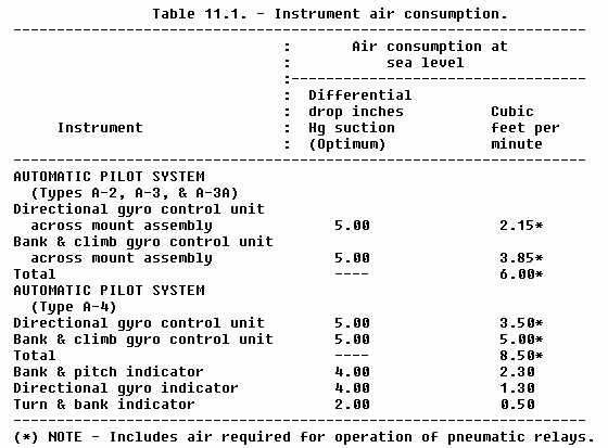
213. INSTALLATION. Mount all instruments so they are visible to the crewmember primarily responsible for their use. Mount self-contained gyroscopic instruments so that the sensitive axis is parallel to the aircraft longitudinal axis. a. Structure. When making structural changes such as adding holes in the instrument panel to mount instruments, refer to chapter 2, paragraph 23a through f of this handbook. Refer to the aircraft manufacturer's instructions and Advisory Circular 43.13-1A, "Acceptable Methods, Techniques, and Practices - Aircraft Inspection and Repair," chapter 2, section 3, for methods and techniques of retaining structural integrity. b. Plumbing. Refer to the manufacturers instructions for fabrication, routing and installation of instrument system lines. Advisory Circular 43.13-1A provides information regarding the installation and fabrication of aircraft plumbing. c. Vacuum Source. Minimum requirements for installation and performance of instrument vacuum systems are covered in the applicable FAR Airworthiness Standards under "Instruments: Installation." (1) In the absence of specific requirements for vacuum pump installation, refer to FAR Part 25, section 25.1433 for guidance. It is desirable to install a "T" fitting between the pump and relief valve to facilitate ground checking and adjustment of the system. (2) When a venturi tube power source is used, it should not be taken for granted that a venturi will produce sufficient vacuum to properly operate one or more instruments. Many of the venturi tubes available for aircraft have a flow rate of approximately 2.3 cubic feet per minute at 3.75 inches of mercury (in Hg) vacuum. Therefore, it is essential that the vacuum load requirements be carefully evaluated. (3) Vacuum loads may be calculated as follows: (a) Gyroscopic instruments require optimum value of airflow to produce
their rated rotor speed. For instance, a bank and pitch indicator requires
approximately 2.30 cubic feet per minute for its operation and a resistance
or pressure drop of 4.00 inches Hg. Therefore, operating an instrument
requiring 4.00 inches Hg from one venturi would be marginal. Similarly,
the directional gyro indicator consumes approximately 1.30 cubic feet per
minute and a pressure drop of 4.00 in Hg. The turn and bank indicator has
a flow requirement of 0.50 cubic feet per minute and reaches this flow
at a pressure drop of 2.00 inches Hg. The above instruments are listed
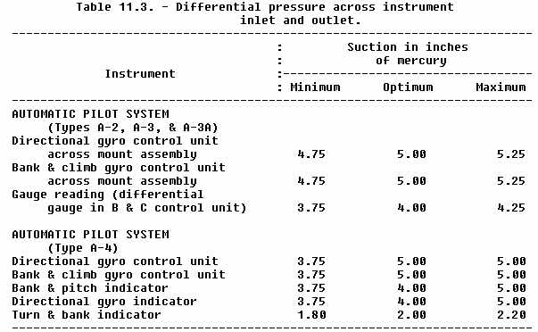
in Tables 11.1 and 11.3. Optimum values are shown in Table 11.3. It should
be noted that the negative pressure air source must not only deliver the
optimum value of vacuum to the instruments, but must also have sufficient
volume capacity to accommodate the total flow requirements of the various
instruments which it serves.
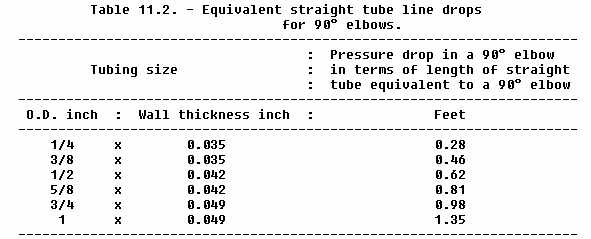
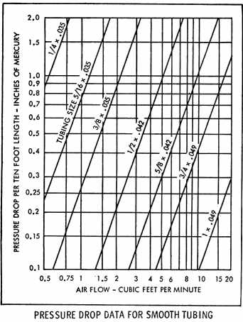
(b) To calculate the flow requirements of a simple vacuum system, assume four right-angle elbows and 20 feet of line (1/2 O.D. x 0.042) tubing. 1 Assume the flow requirements for:
2 The pressure drop for one 90° 1/2 inch O.D. x 0.042 elbow is
equivalent to 0.62 feet of straight tubing, figure 11.1.
Therefore, the pressure drop of four 90° elbows is equivalent to 2.48
feet of tubing.
3 Determine the pressure drop through 22.48 feet (20 feet + 2.48 equivalent feet) of 1/2 O.D. x 0.042 tubing at 4.10 CFM flow. From figure 11.1, pressure drop per each 10 foot length = 0.68 inches Hg. Divide 22.48 feet of tubing by 10 to obtain the number of 10 foot sections, that is, 22.48 divided by 10 = 2.248. Multiply the number of sections by 0.68 inches Hg to obtain the pressure drop through the system. (0.68 x 2.248 = 1.53 inches Hg) 4 The pump must therefore be capable of producing a minimum pressure differential of 5.53 inches Hg, that is, 4.00 inches Hg for maximum instrument usage + 1.53 inches Hg (determined) at a flow of 4.10 cubic feet per minute. Table 11.3. - Differential pressure across instrument
d. Filter. Filters are used to prevent dust, lint and other foreign matter from entering the instrument and vacuum system. Filters may be located at the instrument intake port or at the manifold intake port when instruments are interconnected. Determine that the capacity of the filter is as great or greater than the capacity of the vacuum system. Assure that there is no pressure drop across the filter media. e. Electrical Supply for Instruments. Guidelines for the installation of instrument electrical wiring and power source are provided in Advisory Circular 43.13-1A, chapter 11, sections 2 and 3, and Chapter 16, section 3. NOTE: Strict conformance to the shielding specifications supplied by compass manufacturers is recommended In all installations to eliminate any possibility of spurious signals. f. Instrument Lighting. Instrument lighting must be installed in accordance with the regulations that are applicable to the aircraft type certification requirements. If in some instances the reflection of the lights is unsatisfactory, provide a shield or a means for controlling the intensity of illumination. g. Magnetic Headings. Calibrate magnetic instruments with the powerplants operating. After this initial calibration, switch all nav/com and electrical equipment, such as windshield wipers and defrosters, "on" to determine if any electrical system interference affects the instrument calibration. If the calibration is affected, prepare an instrument placard identifying the compass headings with the equipment "on" and also with the equipment "off." Placard in accordance with paragraph 214f of this chapter. 214. TESTING, MARKING, AND PLACARDING. a. Testing the Venturi Tube-Powered Systems. At normal inflight cruise speed, check the venturi tube-powered system to assure that the required vacuum pressure is being supplied. b. Testing the Vacuum Air Pump Powered System. When the system is powered by vacuum air pumps, check the system while the pumps are operating at their rated rpm and measure the vacuum available to the instruments. c. Testing of Altimeters and Static Systems. When checking the operation of an altimeter static system to determine that the system is free of any contaminating materials, be sure to disconnect the plumbing from all air operated instruments before purging the lines with dry air or nitrogen since the pressure necessary for purging may damage any connected instrument. Static system test procedures are provided in FAR 43, Appendix E. d. Testing electrical supply (instruments). Check the voltage at the instrument terminals and determine that it is equal to the manufacturer's recommended values. e. Fuel, Oil, and Hydraulic (instrument Supply). Measure the fluid pressure at the instrument end of the line to determine whether it is equivalent to that at the pressure source. f. Instrument Markings and Placards. When additional instruments are installed they must be appropriately marked. Refer to the applicable CAR/FAR under "Markings and Placards" for specific instrument marking and placard requirements. 215. - 240. [RESERVED] |
||||||||
| ©AvStop Online Magazine Contact Us Return Home |
