
![]()
![]()
|
|
|
|
Chapter 12. Litter, Berth, And Cargo Tiedown Device Installations
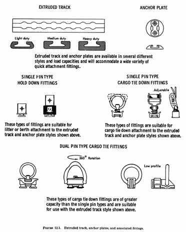
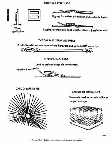
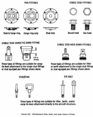
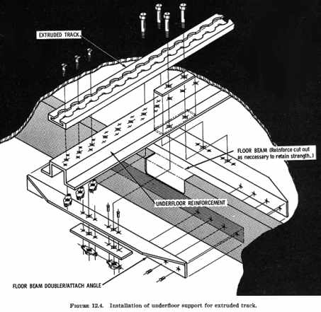
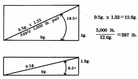
c. Use only materials that are at least flame resistant for covering of floors, litters, or berths. Refer to the applicable airworthiness standards for the aircraft involved to determine the required flame resistant qualities. For aircraft in air taxi or other commercial operations, refer to the applicable operating rule for special requirements regarding fire protection, cargo bins, location of cargo with respect to passengers, cargo compartment, or aisle width. 243. FABRICATION AND INSTALLATION. a. Litters and berths may be fabricated from tubing, sheet metal, extrusions, canvas, webbing, or other suitable material, using acceptable methods, techniques, and practices. (Reference Advisory Circular 43.13-1A "Acceptable Methods, Techniques, and Practices - Aircraft Inspection and Repair"). Commercially available litters or stretchers may be utilized provided they meet installation and load criteria. Provide a padded end board, canvas diaphragm, or other means at the forward end of each litter or berth that will withstand the total forward static test load. Safety belts used for litters and berths installed parallel to the aircraft's longitudinal axis are not required to withstand forward loads as these loads are to be taken up by the padded end boards. Design litters or berths intended for adults for occupants weighing at least 170 pounds. In those instances where litters or berths are for children, design the installation for the maximum intended weight. See paragraph 247 for placarding. Provide approved seats for any cabin attendants or other passengers that will be carried when litters are installed. b. Cargo tiedown devices may be assembled from webbing, nets, rope, cables, fittings, or other material which conforms to NAS, TSO, AN, MIL-SPEC, or other acceptable standards. Use snaps, hooks, clamps, buckles, or other acceptable fasteners rather than relying upon knots for securing cargo. Install tensioning devices or other means to provide a method of tightening and adjusting the restraint system to fit the cargoes to be carried. Provide covers or guards where necessary to prevent damage to or jamming of the aircraft's equipment, structure, or control cables. 244. STRUCTURAL ATTACHMENT. Commercially available seat tracks, rails, or other types of anchor plates may be used for structural attachment, provided they conform to an accepted standard (see chapter 1, paragraph 6). This type of hardware permits a ready means of mounting a wide variety of quick disconnect fittings for litters, berths, and cargo tiedown. Typical examples of such fittings and their attachment are shown in figures 12.1 through 12.5. {See Figure 12.2} {See Figure 12.3} {See Figure 12.4} When installing these fittings, reinforce the existing floorboards and/or other adjacent structure to obtain the necessary load carrying capacity. Seat tracks installed longitudinally across lateral floor beams generally require full length support for adequate strength and rigidity between beam attach points (see figure 12.4). Consider the inherent flexibility of the aircraft structure and install any reinforcement in a manner that will avoid localized stress concentrations in the structural members/areas. Give specific attention to the size, shape, and thickness of the reinforcement, fastener size and pattern, and the effects of any adhesives used. Fittings used for litter, berth, safety belt, and/or cargo tiedown attachment need not be substantiated by static tests if it can be shown that the fitting's rated minimum breaking strength would not be exceeded by the applicable static test loads. Existing racks, rails, or other points used for attachment may be verified by static tests, analysis, or a written statement by the aircraft manufacturer attesting to its adequacy to withstand the necessary loads. For litters which are to be readily installed and removed, it may be desirable to utilize existing seat structure, safety belt attach fittings, seat tracks, or other seat attach fittings. When using such attach points, assure by static tests or manufacturer's written statement that they will not be stressed beyond the loads for which they were originally intended. 245. LOAD FACTORS. Use the load factor established by the aircraft manufacturer for type certification as the basis for substantiating the litter or berth and its attachment to the aircraft structure. Cargo tiedown devices installed within passenger compartments are subject to the same load factors as litter or berth installations. Refer to the applicable operating rules for any additional load factor requirements if the aircraft is to be used for air taxi or other commercial operations. The critical load factors to which the installation is to be substantiated are generally available from the person currently holding the aircraft's Type Certificate (TC). When the TC holder is no longer active, such data may be obtained from the controlling FAA regional engineering office. The addresses of TC holders and FAA controlling regions are given in the FAA publication "Type Certificate Data Sheets and Specifications." 246. STATIC TESTS. It is recommended that static testing be conducted on a duplicate installation in a jig or mockup which simulates the related aircraft structure. Refer to chapter 1, paragraph 3 for static test information. If the actual installation is used for static testing, inspect both the aircraft and the litter, berth, or cargo tiedown device installation thoroughly before releasing to service. Check all members and fittings for cracks, distortion, wrinkles, or elongated holes. Replace all bolts and threaded fittings that are not inspected by magnetic particle or other acceptable N.D.T. inspection process. Inspect riveted joints for tipped rivet heads and other indications of partially sheared rivets or elongated holes. a. For litter and berth installations, compute the up, down, side, fore, and aft static test loads required for substantiation by multiplying the standard passenger weight, 170 pounds, by each of the CRITICAL STATIC TEST LOAD FACTORS. Refer to chapter 1 of this handbook for computation procedures. (For utility category aircraft use 190 pounds, and for litters or berths intended for children use the placarded weight.) Perform tests as necessary to substantiate the complete litter or berth installation for each intended position (forward, aft, or side facing). When testing for a particular load, install or adjust the litter or berth to the most critical position for that load. When the safety belt or harness and/or the padded end board is attached to the litter or berth structure, all loads are to be borne by the litter or berth structure and its attachment fittings. Where these are not attached to the litter or berth structure, substantiate the total litter or berth installation for the loads which would be imposed for that safety belt attachment/end board configuration. b. Cargo Tiedown Installations. All cargo tiedown installations must be tested to the critical ultimate load factor. Refer to chapter 1 of this handbook for computation and testing procedures. When the cargo compartment is separated from the cockpit by a bulkhead that is capable of withstanding the inertia forces of emergency conditions a forward load factor of 4.5 g may be used. All other applications require the use of a 9 g forward load factor. Each cargo tiedown fitting installation must be static tested under forward, side, and up load conditions. Individual fittings may be tested by applying a single pull of 12.6 g forward load at an angle of 18.5° up and 9.5° to the left or right, as applicable, of the aircraft longitudinal axis. For example, assuming a 5,000 pound static pull (rating of a typical tiedown fitting) is applied as described and divided by the g. load factor we find the fitting installation will be capable of restraining a 397 pound load under emergency conditions. {See Equation 1} When a cargo restraining net or cargo container with multiple attachments is used the static load requirements for each tiedown fitting may be divided equally between the fittings. For example, assume that the maximum cargo load to be carried is 1,800 pounds and 10 tiedown fittings are to be used, the static load requirement for each fitting is approximately 2,155 pounds.
9 g x 1.33 x 1,800 pounds
Placard individual tiedowns for the maximum weight to be secured. 247. OPERATING LIMITATIONS, LOADING INSTRUCTIONS, AND PLACARDS. Prepare revisions or supplements to the aircraft's Flight Manual or operating limitations, weight and balance records, and equipment list changes as necessitated by the installation of the litter, berth, or cargo tiedown systems. NOTE - Revisions or supplements to the approved portions of the aircraft's Flight Manual markings, placards, or other operating limitations require FAA engineering approval. Submit the requested changes and supporting data to the local FAA Flight Standards Office for review and processing. Provide instructions covering the installation and use of the litter or cargo restraint systems. For aircraft which require a Flight Manual, incorporate these instructions as a supplement. On other aircraft, provide a placard which references the appropriate instruction. In the instructions, cover such items as removal and reinstallation of seats or other equipment exchanged for litters or cargo restraint systems, use of cargo nets, barrier nets, number and positioning of tiedown straps, maximum load for each compartment or tiedown area, permissible load per square foot, number of tiedown points allowable per foot of track, and maximum height of the load's center of gravity above the floor. a. Cargo Area Placards. Install placards or other permanent markings to indicate the maximum allowable cargo load and weight per square foot limitation for each cargo area. Placard seat tracks as to number of tiedown points permissible per foot of track. Attach a permanent label or other marking on each cargo net, barrier net, and at cargo tiedowns to indicate the maximum cargo weight that the net or attachment will restrain when installed according to the loading instructions. b. Litter and Berth Placards. Install a placard or other permanent marking on each litter or berth indicating its permissible direction of installation (forward, aft, or side facing), passenger weight limitation (if less than 170 pounds), and whether or not the litter or berth may be occupied during takeoffs and landings. 248. - 260. [RESERVED] |
||
| ©AvStop Online Magazine Contact Us Return Home |

