
![]()
![]()
|
|
|
|
Chapter 2. Radio Installations
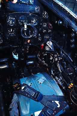
22. EQUIPMENT MANUFACTURER'S INSTRUCTIONS. Installation instructions provided by the aircraft radio manufacturer are acceptable guidelines when adapted to the aircraft in accordance with data contained in this chapter. 23. INSTRUMENT PANEL MOUNTING. Data in this paragraph is supplemented by chapter 2 of AC 43.13-1A, "Acceptable Methods, Techniques, and Practices - Aircraft Inspection and Repair" and is applicable to the installation of radio units in instrument panels. a. Stationary Instrument Panels - Nonstructural and Structural. The stationary instrument panel in some aircraft is primary structure. Prior to making any additional "cutouts" or enlargement of an existing "cutout" determine if the panel is primary structure. If the panel is structural, make additional "cutouts" or the enlargement of existing "cutouts" in accordance with the aircraft manufacturer's instructions, or substantiate the structural integrity of the altered panel in a manner acceptable to the Administrator. Radius all corners and remove all burrs from "cutout" and drilled holes. b. Added Equipment - Stationary Instrument Panel. When radio equipment is to be installed in a stationary panel already supporting instruments, glove compartments, etc., determine the capability of the panel to support the total load. c. Case Support. To minimize the load on a stationary instrument panel, whenever practicable, install a support between the rear (or side) surface of the radio case and a nearby structural member of the aircraft. d. Added Equipment - Shockmounted Panels. When installing radio equipment designed for use in shockmounted panels, total accumulated weight of equipment installed must not exceed the weight carrying capabilities of the shockmounts. Determine that the structure to which the shockmounts are connected is satisfactory for the added weight. e. Existing Factory Fasteners. When possible, utilize existing plate nuts and machine screws provided by the aircraft manufacturer for attachment of the radio case or rack. If additional fastening is required, use machine screws and elastic stop nuts (preferably plate nuts). f. Magnetic Direction Indicator. As a function of the radio installation, determine if it is necessary to compensate the compass. Install a suitable placard which indicates the compass error with the radio(s) on and off. The receiver(s) should be tuned through
the low, middle and higher frequencies to cover all contingencies involving
the operation of relays which would cause electromagnetic induction to
the magnetic compass. When inverters are installed, determine what effect
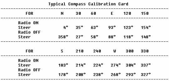
their operation has on the magnetic compass. Maximum acceptable deviation
in level flight is 10° on any heading. The following is an example
of a typical compass calibration card.
{See Figure 2.1 - Typical radio installations in stationary instrument panels.} {See Figure 2.2 - Typical panel mount.} 24. OTHER MOUNTING AREAS. The following are acceptable methods for installing radio equipment at other than instrument panel locations. a. Shockmounted Units. (1) Wood or Composition Flooring. Secure the shockmounted base assembly (suitable to radio unit) directly to the floor using machine screws. Add a doubler to the bottom of the floor thereby sandwiching the composition floor between each shockmount foot and the doubler. Subsequent removal and reinstallation of the shockmount foot will be facilitated if plate nuts are secured to the doubler. Where practicable, use small retaining screws to keep the doubler in position. Install a ground strap between the radio rack and metal structure of the aircraft. {See Figure 2.3 - Typical shockmounted base.} (2) Metal Flooring. Secure the shockmounted base assembly directly to the floor using machine screws, washers, and self-locking nuts. Floor area under and around the radio mounting bases may require installation of doublers or other reinforcement to prevent flexing and cracking. Installation of plate nuts on the floor or doubler will facilitate removal and installation of the shockmounts. Install a ground strap between the shockmount foot and the radio rack. {See Figure 2.4 - Typical shockmounted base.} b. Rigid-Mounted Unit Base. Secure radio mounting base plate(s) to floor (wood, composite, or metal) using machine screws as shown in figure 2.5. Use a reinforcing plate or large area washers or equivalent under wood or composite flooring. When mounting base is secured to wood or composite material, install a ground strap between the base and aircraft metal structure. 25. FABRICATION OF SUPPORTING BRACKETS FOR ATTACHMENT TO STRUCTURE OTHER THAN FLOORING. a. Typical supporting brackets usually consist of a shelf or platform upon which the radio unit mounting base assembly can be installed in the same manner as described in applicable paragraph 24. b. Fabricate bracket in accordance with good aircraft design, layout, assembly practices, and workmanship to obtain results compatible with the airframe structure. Generally the thickness of bracket material will depend on the size or area of the platform and load it must sustain in accordance with provisions set forth in chapter 1 of this handbook. c. Use a rivet size and pattern compatible with the aircraft structure to provide the strength needed to assure support of the loads imposed under all flight and landing conditions. {See Figure 2.6 - Typical underseat installation.} 26. SUPPORTING STRUCTURE REINFORCEMENT. a. Attach equipment supporting structure to the aircraft so that its supported load will be transmitted to aircraft structural members. If direct attachment to existing structure (bulkheads, horizontal stringers, etc.) is not feasible, add the necessary stringers, doublers, bulkhead flange reinforcements, etc., to provide adequate support and assure load transfer to primary structure. b. Placard. Fasten on the shelf or bracket a permanent placard (as the example below) stating the design load which the installed structure has been determined to be capable of supporting.
-----------------------------------
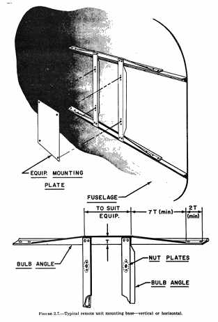
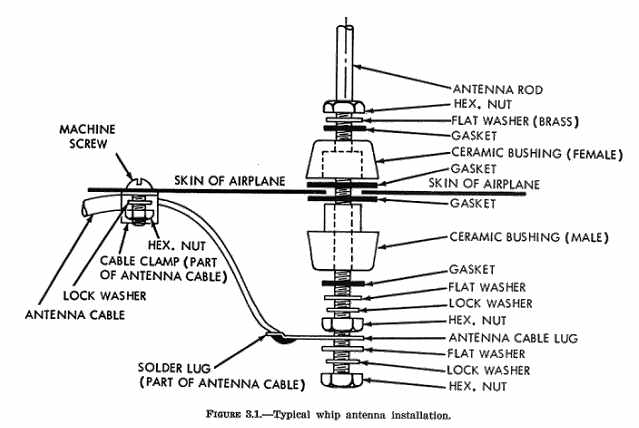
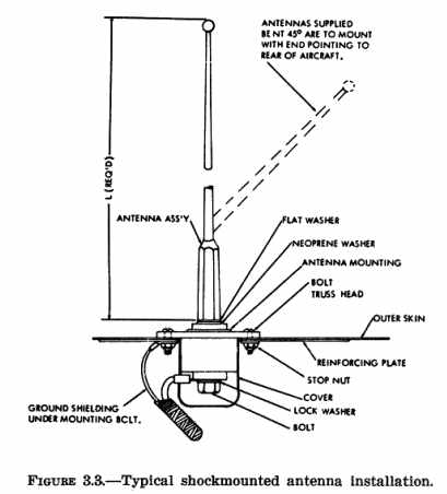
Fabricate platform using 2017T4(17ST) or equivalent. Apply standard aircraft practices for fabrication and installation. The equipment manufacturer mounting bases that meet load requirements and can be utilized are acceptable. 27. ELECTRICAL SYSTEMS. The following data in addition to that shown in chapter 11 in AC 43.13-1A is applicable to radio installations. a. Installation of Wiring. (1) Use a type and design satisfactory for the purpose intended. (2) Install in a manner to be suitably protected from fuel, oil, water, other detrimental substances and abrasion damages. b. Power Sources. (1) Connect radio electrical systems to the aircraft electrical system at a terminal strip, or use a plug and receptacle connection. (2) Radio electrical systems must function properly whether connected in combination or independently. c. Protective Devices. (1) Incorporate a "trip free" resettable type circuit breaker or a fuse in the power supply from the bus. Mount in a manner accessible to a crewmember during flight for circuit breaker resetting or fuse replacement. (2) Select circuit breakers or fuses that will provide adequate protection against overloading of the radio system circuits. (3) Connect all leads in such a manner that the master switch of the aircraft will interrupt the circuit when the master switch is opened. (4) Radio system controls are to provide independent operation of each system installed and are to be clearly placarded to identify their function relative to the unit of equipment they operate. d. Available Power Supply. To preclude overloading the electric power system of the aircraft when additional equipment is added, make an electrical load analysis to determine whether the available power is adequate. Radio equipment must operate satisfactorily throughout the voltage range of the aircraft electrical system under taxi, takeoff, slow cruise, normal cruise, and landing operating conditions. If night and instrument flight is contemplated, compute the electrical load analysis for the above flight regimes under the most adverse operating conditions. {See Figure 2.9 - Typical rail platform installation - aluminum alloy structure.} {See Figure 2.10} e. Wire Bundle Separation from Flammable Fluid Lines. (1) Physically separate radio electric wire bundles from lines or equipment containing oil, fuel, hydraulic fluid, alcohol, or oxygen. (2) Mount radio electrical wire bundles above flammable fluid lines and securely clamp to structure. (In no case must radio electrical wire bundles be clamped to lines containing flammable fluids.) f. Cable Attachment to Shockmounted Units. (1) Route and support electrical wire bundles and mechanical cables in a manner that will allow normal motion of equipment without strain or damage to the wire bundles or mechanical cables. g. Radio Bonding. It is advisable to bond radio equipment to the aircraft in order to provide a low impedance ground and to minimize radio interference from static electrical charges. When bonding is used, observe the following: (1) Keep bonding jumpers as short as possible. (2) Prepare bonded surfaces for best contact (resistance of connections should not exceed 0.003 ohm). (3) Avoid use of solder to attach bonding jumpers. Clamps and screws are preferred. (4) For bonding aluminum alloy, use aluminum alloy or tinned or cadmium plated copper jumpers. Use brass or bronze jumpers on steel parts. (5) When contact between dissimilar metals cannot be avoided, put a protective coating over the finished connection to minimize corrosion. {See Figure 2.11.} h. Radio Interference. Radio interference generated by aircraft components can be eliminated or reduced by exercising proper precautions. The following paragraphs contain two major sources of interference which affect audio reception. (1) Ignition system interference can be minimized with shielding. To be effective, all parts of the ignition system should be shielded in metal in order to eliminate noise resulting from RF radiation. (a) A metallic braid covering and special end connectors are effective between the magneto and shielded type spark plugs. (b) Shield the primary lead to the magneto. (c) Provide a shielded metal cover for the magneto if it is not of a shielded type. (d) Provide a tight metal-to-metal contact of all connections in the shielding system. (e) If it is not feasible to shield the engine ignition system, the engine ignition noise may be suppressed by replacing the spark plugs with resistor spark plugs of a type approved for the engine. (f) If it is found that despite shielding of the ignition wiring and plugs an intolerable noise level is present in the radio system, it may be necessary to provide a filter between the magneto and magneto switch to reduce the noise. This may consist of a single bypass capacitor or a combination of capacitors and choke coils. When this is done, the shielding between the filter and magneto switch can usually be eliminated and the special shielded magneto switch need not be used. (g) Supporting brackets and wiring details for magneto filters should be in conformance with standard aircraft electrical practice. The reliability of the magneto filter installations should be at least equivalent to that of the remainder of the magneto ground lead installation. (2) Inverter interference is noticeable by a constant noise or hash induced and amplified by the audio circuits of the communication or navigation systems. This noise level can reach such a magnitude that all intelligence of audio reception is lost. Inverter interference can be effectively minimized or eliminated by observing the following precautions during installation: (a) Locate the inverters in an area separated from other electronic equipment. (b) Assure that the inverter input and output wires are separated. (c) Shield the inverter output wires and ground the shields at the inverter end only. (d) Make sure the inverter case is adequately bonded to the airframe. i. Mutual Radio Frequency Interference in DME/ATC Radar Beacon Systems. Distance measuring equipment (DME) and ATC radar beacon (transponder) systems operate within the same frequency range. Therefore, simultaneous operation of two or more of these systems may result in mutual RF interference. Certain makes of DME and transponder equipment have intersystem suppressor circuitry designed to eliminate mutual interference. When such connections are provided, follow the manufacturer's recommendations for use and wire bundle installation. 28. EMERGENCY LOCATOR TRANSMITTER (ELT) INSTALLATIONS. The ELT unit should be attached to the airframe or other solid structures. Airframe preparation for either vertical or shelf type mountings is displayed in figures 2.7 and 2.8. The equipment manufacturer mounting bases that meet load requirements and can be utilized are acceptable. The installation of the ELT antenna should be located as far as practicable from other installed antennas. Methods for securing whip-type antennas to the structure are shown in figures 3.1 and 3.3. Follow the installation procedures when available. 29. - 35. [RESERVED] |
||||
| ©AvStop Online Magazine Contact Us Return Home |
