Chapter 3. ANTENNA INSTALLATIONS
| 36. PERFORMANCE.
For proper performance, it is important that the radio equipment manufacturer's
instructions be carefully followed in matching and coupling the antenna
to the radio equipment.
a. The location of the antenna is of primary importance. When selecting
a mounting position, consideration should be given but not limited to the
following:
(1) Obstruction to signal reception by aircraft or aircraft
components.
(2) Ignition noise (RF radiation pickup).
(3) Vibration.
(4) Flutter.
(5) Instrument static source interference. |
|
b. Attach antenna mounting (masts, base receptacles, and/or supporting
brackets) so that the loads imposed (for example, air, ice, etc.) are transmitted
to the aircraft structure.
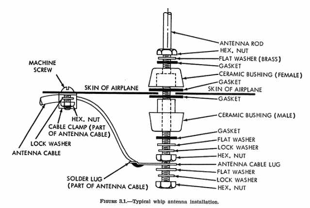
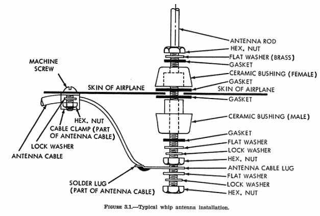
37. VHF ANTENNA - WHIP.
a. Locate this type antenna so that there is a minimum of structure
between it and the ground radio stations. The antenna may be mounted on
the top or bottom of the fuselage. It is not advisable to mount the antenna
on the cowl forward of the windshield because a lightning strike might
possibly blind the pilot.
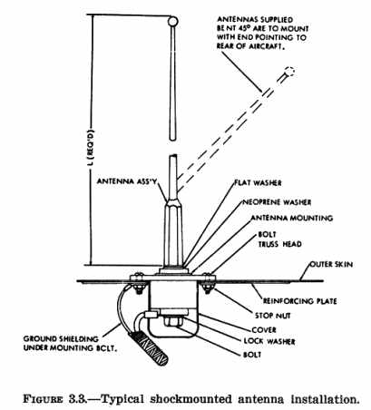
b. Methods of securing whip antennas to the structure are shown in figures
3.1
and 3.3.
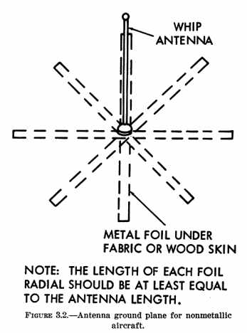
c. On fabric covered aircraft or aircraft with other types of nonmetallic
skin, the manufacturer's recommendations should be followed in order to
provide the necessary ground plane. An acceptable method of accomplishing
this is by providing a number of metal foil strips in a radial position
from the antenna base and secured under the fabric or wood skin of the
aircraft. (See figure 3.2)
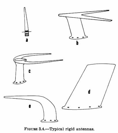
38. VHF ANTENNA - RIGID.
a. When it is necessary to cover a broader frequency range than can
be covered by a whip antenna, a blade type should be used because it is
resonant over a much broader frequency range. However, a broadband antenna
is not as efficient as a small diameter whip antenna and, accordingly,
should not be used with relatively low output transmitters (under 5 watts).
(1) The antennas shown in figure 3.4 are normally
installed at a point on the fuselage directly above the cabin or baggage
compartment.
When a rigid antenna is installed on the vertical stabilizer, evaluate
the flutter and vibration characteristics of the installation.
(2) The approximate drag load an antenna is required to withstand can
be determined by the following formula:
D = 0.000327 x A x V^2
(The formula includes a 90 percent reduction factor for streamline shape
of antenna.)
Where D is the drag load on the antenna in pounds,
A is the frontal area of the antenna in square feet, and
V is the Vne of the aircraft in mph.
The frontal area of typical antennas are approximately as follows:
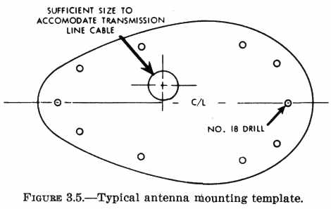
b. Installation of Rigid Antennas.
(1) Place a template similar to figure 3.5 on
the fore-and-aft centerline at the desired location. Drill the mounting
holes and the correct diameter hole for the transmission line cable in
the fuselage skin.
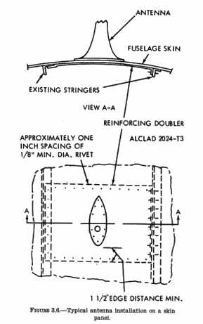
(2) Install a reinforcing doubler of sufficient thickness to reinforce
the aircraft skin. The length and width of the plate should approximate
that illustrated in figures 3.6 or 3.8.
(3) Install antenna on fuselage, making sure that the mounting bolts
are tightened firmly against the reinforcing doubler, and that the mast
is drawn tight against the gasket.
When a gasket is not used, seal the crack between the mast and fuselage
with a sealer, such as zinc chromate paste or equivalent.
(4) Route transmission line cable to the receiver, secure the cable
firmly along its entire length at intervals of approximately 2 feet, and
take care to prevent fouling of control cables.
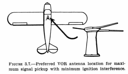
39. VHF NAVIGATION RECEIVING ANTENNAS.
Locate antennas for omnirange (VOR), and instrument landing system (ILS)
localizer receivers at a position on the aircraft where they will have
the greatest sensitivity for the desired signals and minimum response to
undesired signals such as electrical energy radiated by the engine ignition
system. A good location for the VOR localizer receiving antenna on many
small
airplanes is over the forward part of the cabin. Mount the rigid V-type
antenna so that the apex of the "V" points forward and the plane of the
"V" is level in normal flight. {See Figure 3.7.}
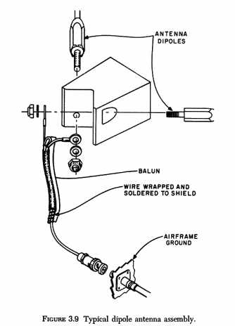
a. VOR Antenna Balun and Transmission Lines.
A dual element or balanced antenna system requires a balun or an impedance
matching device for maximum signal transfer into an unbalanced coaxial
cable. Rigid antennas, as displayed in figure 3.4,
incorporate a balun as an integral component of the antenna assembly. Follow
the manufacturer's installation procedures and assure that the balun is
properly grounded to the airframe. Refer to AC 43.13-1A "Acceptable Methods,
Techniques, and Practices - Aircraft Inspection and Repair" chapter 11,
for acceptable bonding practices. {See Figure 3.9.}
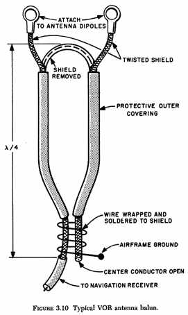
(1) {(2) in original - Ed.} Figure 3.10 is an
illustration of a typical VOR antenna balun. A balun made from a section
of the transmission line functions as a tuned circuit or transformer which
produces a standing wave ratio to provide the desired matching impedance.
When the antenna is matched to the line, the line measurement in multiples
of wave lengths is not critical.
(2) Radio wave velocity is less in a cable than in air; therefore, the
wave length in cable will be shorter than in air. Appropriate test equipment
must be used for transmission line measurements because the physical and
electrical lengths of lines are not always equal.
(3) The transmission line should be kept as short as possible. Any bends
in the cable should have at least a 3 inch radius. Follow the equipment
manufacturer's recommendations regarding transmission lines and lengths.
b. Assembly of Coaxial Cable Connectors.
Optimum performance of a radio system is dependent upon the coaxial
cable connector assembly. Follow the manufacturer's assembly instructions.
Assure that the cable is not distorted or flattened when cutting. The electrical
characteristics of the cable change when flattened or bent sharply.
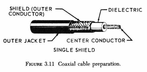
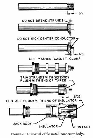
(1) To remove the outer jacket, cut with a sharp knife around the circumference,
then make a lengthwise slit and peel off the outer jacket. Do not nick,
cut or damage the shield.
(2) Comb out the braid and bend back to expose the dielectric. Use a
sharp knife to cut the dielectric around the circumference, not quite through
to the center conductor. Do not nick or cut the conductor. Remove the dielectric
by twisting and pulling. {See Figure 3.11.}
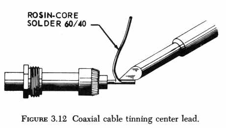
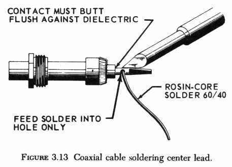
(3) Solder the contact to the center conductor. Use a clean, well-tinned
soldering iron. {See Figure 3.12.}
(4) Do not apply heat too long as this will swell the dielectric and
make it difficult to insert into the body of the connector.
{See Figure 3.13.}
(5) Install connector body and tighten until secure. Do not over tighten
as this will distort the cable. {See Figure 3.14.}
(6) Use only the crimping tool recommended by the manufacturer, or an
equivalent tool when installing connectors which utilize a crimp-type contact.
c. Dual VOR/NAV Receiver Installations.
Two VOR navigation receivers can be connected to a common VOR antenna.
This is accomplished by utilizing a coaxial tee connecter (UG-274 A/U)
and matched 0.5 wavelength coaxial cable lengths connected from the tee
connector to the respective VOR receivers. Typical cable lengths are from
22 to 35 inches and multiples of these lengths. Another method of coupling
two VOR navigation receivers to a common antenna is by utilizing a device
called a coupler or diplexer. This device,
in addition to impedance matching, also provides isolation between
VOR navigation receivers while keeping line insertion losses at a minimum.
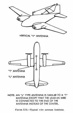
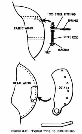
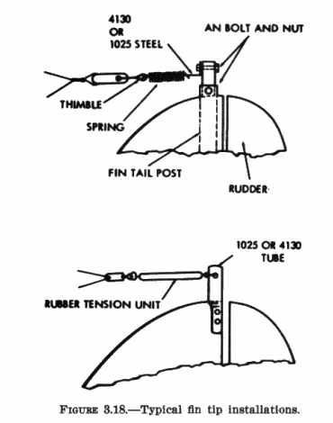
40. RANGE RECEIVING ANTENNAS.
Mount "T", "L", or "V" antennas on top or bottom of the aircraft with
approximately 1 foot clearance from the fuselage and wings. Typical wire
antenna installations are shown in figures 3.15
through 3.19. {See Figure 3.16}
{See Figure 3.17} {See Figure 3.18}
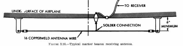
41. MARKER RECEIVING ANTENNA.
The marker receiver operates at a frequency of 75 MHz. In order to keep
to a minimum the number of antennas on the aircraft, the marker receiver
may utilize the same antenna as the range receiver if that antenna is mounted
on the underside of the aircraft. However, both receivers should include
provisions to permit simultaneous operation without interference. A whip
or other vertical type of antenna should not be used for marker reception
since the ground facility transmits from a horizontally polarized antenna.
42. ATC RADAR BEACON (TRANSPONDER) AND DISTANCE MEASURING EQUIPMENT
(DME) ANTENNAS.
Locate these antennas at an unobstructed location on the underside of
the fuselage, preferably at the lowest point of the aircraft when in level
flight. To the extent practicable, mount the antenna so that the base is
horizontal when the aircraft is in cruise attitude.
a. Installation.
Mount the antennas at least 36 inches away from obstructions and as
far as possible from other antennas. Tests have shown that the location
of the antenna with respect to obstructions is of greater importance than
having the antenna installed in a vertical position. However, signal strength
and pattern become noticeably affected as the angle of the antenna approaches
45° from the desired vertical position. On fabric covered aircraft
or aircraft with other types of nonmetallic skin, it will be necessary
to provide a flat metallic surface or "ground plane" extending at least
12 inches in all directions from the center of the antenna. Be sure the
antenna makes a good, direct electrical connection with the ground plane.
Install gaskets, pressurization seals, and/or sealant as required. {See
Figure 3.19.} {See Figure 3.20.}
b. Dual System Installations.
When dual ATC radar systems, dual DME systems, or combinations of these
systems are installed, determine that the separation between their respective
antennas is within the manufacturers prescribed limits. (See paragraph
2-7i for mutual interference in DME and ATC radar beacon systems.)
c. Antenna Cable.
Route the antenna cable in the most direct path practicable. Since losses
can be relatively high at these frequencies, follow the equipment manufacturer's
recommendations regarding transmission lines and lengths.
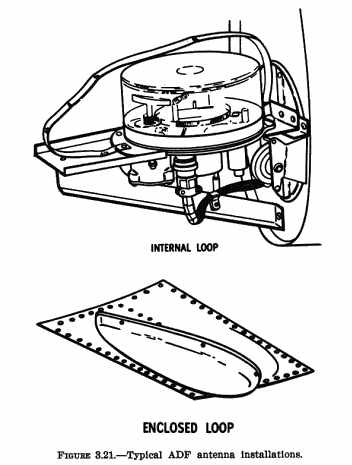
43. DIRECTION FINDING ANTENNAS (100 to 1750 KHz).
Manual or automatic loop-type antennas are used with direction finding
receivers. The loops are designed for use with a particular receiver. Connecting
wires between the loops and receivers are also designed for the specific
equipment. Accordingly, only components meeting the specification characteristics
of the receiver manufacturer should be used.
a. Loops enclosed in streamlined housings or exposed loops are satisfactory
for external mounting on an aircraft. Loops may also be flush mounted on
the aircraft when proper attention is given to avoid interference from
metallic structure and skin of the aircraft. {See Figure 3.21.}
b. Sense antennas are used to resolve radio bearing ambiguity in direction
finding systems. The sense and its leadin must be matched to the input
capacitance of the ADF receiver. The sense antenna capacitance is a function
of length, spacing between antenna and fuselage, and leadin capacitance.
To achieve this antenna/receiver capacitance match, it is important that
the sense antenna be installed in accordance with the ADF manufacturer's
recommendations for the particular make and model of aircraft.
c. Installation kits are designed for either top or bottom fuselage
mounting of loop and sense antennas, or a combination of these two locations.
Particular attention should be paid to the manufacturer's installation
instructions for antenna location (top or bottom) and loop output connections,
in order to prevent 180° errors in bearing indications.
d. Optimum ADF performance, is achieved when the "T", rather than the
"L", type of sense antenna is used, (see figure 3.15).
The "T" type has a noise canceling effect due to the antenna cable being
connected in the center of the antenna. The "L" type antenna has directional
characteristics and may not produce a definite station passage indication
as the "T" type does. A whip antenna of a type and dimension recommended
by the equipment manufacturer may be used in place of the "T" or "L" types.
Methods of installing a whip antenna are shown in figures 3.1,
3.2,
and 3.3.
e. Because the ADF receiver is susceptible to aircraft radiated noise,
antenna leadins should be routed so that they are kept away from electric
power cables, alternators, solid state power supplies, anticollision lights,
pulse transmitting equipment, etc. They may be routed against airframe
members for extra shielding.
f. Loopins should be of the recommended type and length. The length
of leadin specified by the manufacturer for a particular installation may
be excessive for the physical dimensions between the antenna and receiver.
Excessive leadin should not be trimmed, but should be coiled to take up
the extra length. Do not coil excess cable in any area subject to electrical
noise.
g. After completing the installation, it is essential that the loop
be calibrated. One acceptable means of compliance is contained in AC 43.13-1A.
chapter 15, section 6, paragraphs 848 through 853.
44. ANTENNA INSTALLATION ON PRESSURIZED AIRCRAFT.
The use of doublers, to reinforce the aircraft skin to support antennas,
is previously described in this chapter. The material contained in this
paragraph concerns the methods of applying sealant to guard against the
passage of air, liquids, and vapors from pressurized structures.
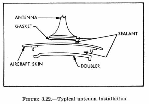
a. Typical Antenna Installation Procedure.
When the attaching parts and the antenna are ready for installation,
clean all faying surfaces with a cleaning solvent. Clean a larger area
than that to which sealant is to be applied. Remove the solvent from the
faying surfaces by blasting with dry air and wiping with a clean soft cloth.
(1) Coat the affected area with the primer specified by the sealant
manufacturer.
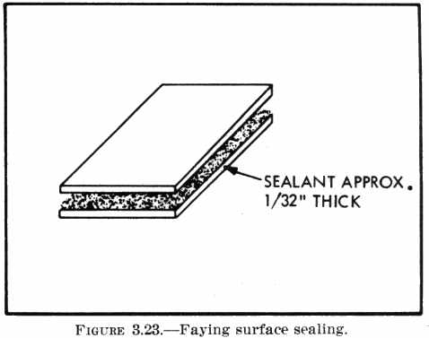
(2) Apply the sealant to one surface, using a spatula or brush, and
spread it over the entire faying surface until a uniform thickness of approximately
1/32 inch is obtained. (See figure 3.22 and 3.23.)
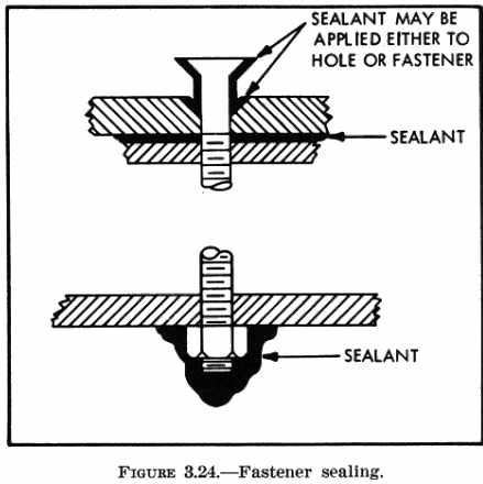
(3) Place the component parts together and install the required fasteners.
If permanent fasteners cannot be installed, use temporary fasteners to
hold the component parts together until the sealant has cured. Install
permanent fasteners with fresh sealant by dipping the fastener in sealant
or by filling the fastener hole with sealant. (See figure 3.24.
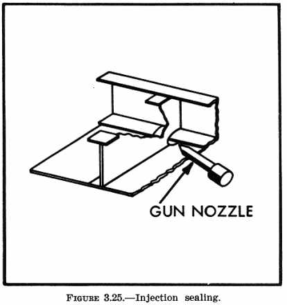
(4) Fill holes and joggles by injecting the sealant into the voids and/or
cavities. This method is used where the sealant cannot be applied with
a spatula or brush. Figure 3.25.
(5) Allow the sealant to cure, then remove excess sealant from the periphery
of the antenna using a nonmetallic scraper.
Warning
Sealants may contain toxic, and/or flammable components. Avoid inhalation
of vapors. Supply adequate ventilation and provide a suitable exhaust system.
Wear approved respiratory protection while using these materials in confined
areas. Do not allow the sealant to come in contact with the skin or eyes.
Insure that no source of ignition is present in the working area.
b. High Speed Aircraft.
The sealant methods described should be used to prevent moisture or
water from entering the aircraft and the expulsion of air and vapors when
the aircraft structure is pressurized.
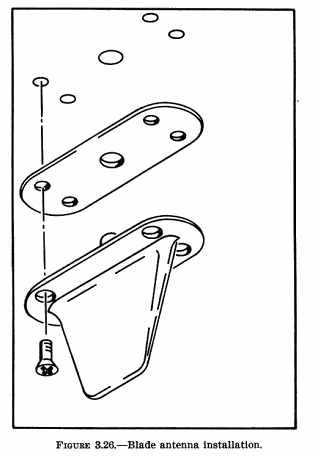
(1) Figure 3.26 displays a blade type antenna
mounted on a flat surface using a sealing gasket. This type of installation
does not require the application of a sealant.
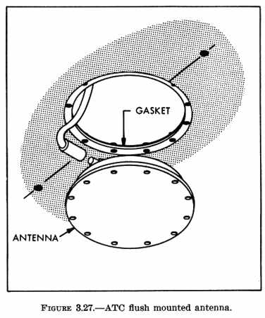
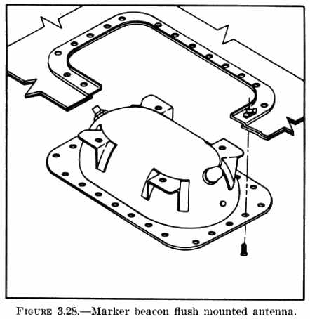
(2) Figures 3.27 and 3.28
display two types of flush mounted antennas. The antenna unit and fiberglass
cover are manufactured as one integral assembly.
(3) Flush mounted antennas installed on a vertical fin are normally
part of the primary structure. The radiating elements of the antenna and
the fiberglass cover are individual units.
(a) Clean all metal surfaces necessary to insure good electrical bonding
contact between the antenna mounting surface and the aircraft structure.
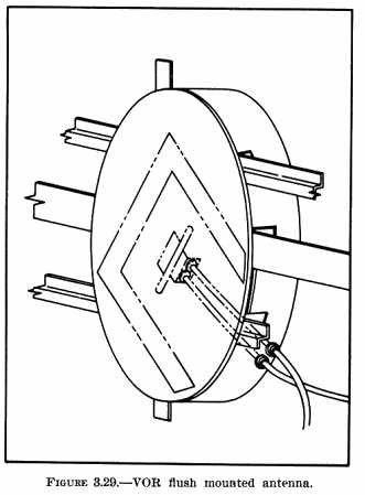
(b) After the fiberglass cover is installed, sealer may be applied to
fill the space between the fiberglass cover and skin of the vertical fin.
Figure 3.29 displays one-half of a vertical fin
antenna installation. An identical installation is required on each side.
45. - 50. [RESERVED]