
![]()
![]()
|
|
|
|
Chapter 4. Anticollision And Supplementary Light Installations
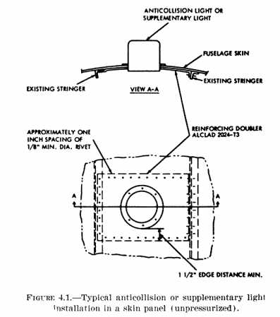
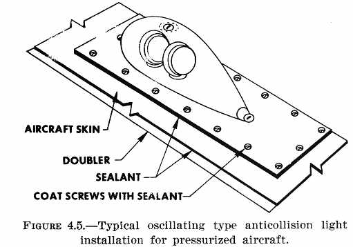
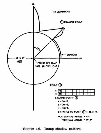
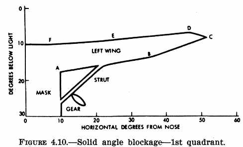
52. INTERFERENCE. a. Crew Vision. Partial masking of the light may be necessary to prevent direct or reflected light rays from any anticollision or supplementary light from interfering with crew vision. Determine that the field of coverage requirements are met. An acceptable method of preventing light reflection from propeller disc, nacelle, or wing surface is an application of nonreflective paint on surfaces which present a reflection problem. Perform a night flight check to assure that any objectionable light reflection has been eliminated. Enter a notation to that effect in the aircraft records. b. Communication and Navigation. Assure that the installation and operation of any anticollision/supplementary light does not interfere with the performance of installed communication or navigation equipment. Capacitor discharge light (strobe) systems may generate radio frequency interference (RFI). This radiated interference can be induced into the audio circuits of communication or navigation systems and is noticeable by audible clicks in the speaker or headphones. The magnitude of the RFI disturbance does not usually disrupt the intelligence of audio reception. c. Precautions. RFI can be reduced or eliminated by observing the following precautions during installation of capacitor discharge light systems: (1) Locate the power supply at least three (3) feet from any antenna, especially antennas for radio systems that operate in the lower frequency bands. (2) Assure that the lamp unit (flash tube) wires are separated from other aircraft wiring placing particular emphasis on coaxial cables and radio equipment input power wires. (3) Make sure that the power supply case is adequately bonded to the airframe. (4) Ground the shield around the interconnecting wires between the lamp unit and power supply at the power supply end only. 53. MARKINGS AND PLACARDS. Identify each switch for an anticollision/supplementary light and indicate its operation. The aircraft should be flight tested under haze, overcast, and visible moisture conditions to ascertain that no interference to pilot vision is produced by operation of these lights. If found unsatisfactory by test, or in the absence of such testing, a placard should be provided to the pilot stating that the appropriate lights be turned off while operating in these conditions. 54. ELECTRICAL INSTALLATION. Install an individual switch for the anticollision light or supplementary light system that is independent of the position light system switch. Data for the installation of wiring, protection device, and generator limitations is contained in chapter 11 of Advisory Circular 43.13-1A, "Acceptable Methods, Techniques, and Practices - Aircraft Inspection and Repair." Assure that the terminal voltage at each light is within the limits as prescribed by the manufacturer. 55. ALTERATION OF STRUCTURE. a. The simplest light installation is to secure the light to a reinforced fuselage skin panel. The reinforcement doubler shall be of equivalent thickness, material, and strength as the existing skin. (Install as shown in figure 4.1.) b. When a formed angle stringer is cut and partially removed, position the reinforcement doubler between the skin and the frame. Doubler to be equivalent to the stringer in thickness and extend lengthwise beyond the adjacent fuselage frames. The distance between the light and the edge of the doubler is twice the height of the doubler flange. (See figure 4.2 for typical installation.) c. Engineering evaluation is required for installations involving the cutting of complex formed or extruded stiffeners, fuselage frames, or pressurized skin of pressurized aircraft. d. Vertical stabilizer installations may be made on aircraft if the stabilizer is large enough in cross section to accommodate the light installation, and aircraft flutter and vibration characteristics are not adversely affected. Locate such an installation near a spar, and add formers as required to stiffen the structure near the light. (A typical installation is shown in figure 4.3.) e. Rudder installations are not recommended because of the possible structural difficulties. However, if such installations are considered, make an engineering evaluation to determine whether the added mass of the light installation will adversely affect the flutter and vibration characteristics of the tail surfaces. f. Pressurized Aircraft Installation. Doubler installation to reinforce the aircraft skin previously described in this chapter is adaptable to pressurized structure with the application of sealant. Sealant is used to prevent moisture, or water from entering the aircraft and the expulsion of air when the aircraft structure is pressurized. (1) Sealant procedures for aircraft skin reinforcing doubler and doubler fasteners are contained in paragraph 44, chapter 3 of this manual. The aircraft manufacturer's data may recommend the specific sealant to be used and provide instructions for the application. (2) Figures 4.4 and 4.5 illustrate two different designs of anticollision light assemblies. The application of sealant is required when either type of light assemblies is installed. Sealant procedures would be identical for installation of a capacitor discharge (strobe) light system. Caution Sealant and solvents may contain toxic and/or flammable components. Avoid inhalation of vapors and supply adequate ventilation. Wear appropriate respiratory protection while using these materials in confined areas. Avoid contact with the skin and eyes. 56. GUIDELINES FOR INSTALLATIONS. a. Prior Approval. Due to the complexity of measurements for intensity, field of coverage, and color, evidence of FAA approval should be obtained from the light manufacturer before installation. b. System Performance. (1) Field of Coverage. Evidence of FAA approval for "field of coverage" should be obtained from the light manufacturer before installation. To insure that the manufacturer's approved field of coverage is applicable to an installation, his mounting tolerance should not be exceeded. (2) Obstructed Visibility. Measure all solid angles of obstruction within the required field of coverage. For multiple light installations, coverage between the mounting levels is not necessary. When a multiple light installation is being evaluated, shadows for each light should be measured independently, and only shadow areas repeated in each independent measurement (overlap) should be counted. Methods for determining the amount of obstructed visibility are given below; however, other methods can give acceptable results. (a) Wall Shadows. This procedure is applicable to installations where shadows from light obstructions appear on a vertical surface such as a hangar wall. Validity is based on two facts: (1) that a vertical surface can approximate a sphere surface if the distance from the light is considerable, and the shadow is reasonably small, and (2) that sphere surface area can be converted to steradians by dividing by the radius squared. 1 - Position the aircraft in a darkened hangar so that longitudinal axis is perpendicular to a hangar wall. Level as for weight and balance. To keep measure errors low, the distance from light to wall should be as great as practicable considering hangar size. The distance should not be less than 20 feet. 2 - Turn on the lights and measure the area of wall shadows. Sufficient points should be marked and identified so that the shadow pattern can be transferred to graph paper for accurate evaluation. Area can be found by counting squares on the graph or by using a planimeter. Measurements should include areas of transition from shadowed to lighted areas. For top light measurements on multiple light installations, only shadows above the level of the top light should be considered. 3 - Compute the solid angle obstruction in steradians, by dividing each shadow area by the square of the distance from the center of the area to the light. 4 - Evaluate the results to determine if the system consists of enough lights to illuminate the vital areas around the aircraft, considering the physical configuration and flight characteristics of the aircraft. The field of coverage must extend in each direction within at least 30° above and 30° below the horizontal plane of the aircraft, except that there may be solid angles of obstructed visibility totalling not more than the requirements of paragraph .1401(b) of the applicable airworthiness regulations. 5 - For installations where shadows are restricted to directly aft and centered about the longitudinal axis, the following procedures apply: a - Establish a point on the wall which corresponds to a line parallel to the longitudinal axis and through the light associated with the shadow. b - Measure the distance from the light to the point and determine the area representing 0.15 steradians (A = 0.15 x d^2). The distance (d) should be at least 20 feet. c - Draw a circle, with the established point as the center, having an area equal to that found in b above. d - If the shadow falls within this circle, its position is acceptable. For multiple light installations, consider only the shadow above light level. e - If the shadow is partially out of the circle, the shape of the 0.15 steradian area may be varied, but the established point should remain at the center of the area (centroid). (b) Ramp Shadows. This procedure is applicable to shadows which appear on a horizontal plane such as a flat level ramp and will be associated with a top mounted light and a 0.5 steradian limit. Area measurements as described in the wall shadow method should not be used. Some error is inherent, because horizontal angles are measured on a plane displaced from the light source. To compensate for these measurement errors, a table (figure 4.8) is furnished to convert from measured solid angles to true solid angles. A term "square degrees" is used to aid in the discussions of solid angle measurements. 1 - If no masking is required, remove the red cover and attach its clamp ring to the light base. If masking is used, obtain a clear cover and install it with a duplicate mask. 2 - Center the aircraft on the largest available dark ramp. A minimum of 50 feet radius of clear ramp space will usually be needed. If the installation is symmetrical, clear ramp space will be needed on one side only. Level the aircraft as for weight and balance check. Trim the flaps, rudder, elevator and ailerons. With jacks in place, raise the gear if the measurement results would otherwise be affected. 3 - Chalk the following marks on the ramp: a - A reference point directly below the light. b - A circle centered on this reference point having a radius equal to 1.732 times the height of the light above the point. (The circle represents area beyond the minus 30° vertical limit and does not require lighting.) c - A line parallel to the aircraft longitudinal centerline which passes through the reference point. d - A line perpendicular to the above line, which also passes through the reference point. 4 - At night, turn on the anticollision light and chalk all shadow patterns (except jack shadows) which appear outside the circle. If the light rotates so as to cause the shadows to oscillate, lay twine along the outermost edge of the shadow, and chalk along the line. 5 - Move the aircraft to facilitate area measurements. Measure, sketch, and chart the ramp marks and other information as shown in Figure 4.6. Measure enough points along the shadow patterns to accurately describe them. Make enough sketches to include all shadows. 6 - Convert the above measurements to a graph showing vertical degrees vs. horizontal degrees as shown in Figure 4.7 (first quadrant). The second quadrant will have to be measured also to obtain the total shadow area for one side. If the shadow pattern is symmetrical, no other measurements will be necessary. Use 1 degree for each space on the graph paper and count the square degrees of shadow. A total of 1,642 or less is within limits. A total of 1,872 or more is out of limits, and if possible, should be reduced by adding or moving a light, or by trimming a mask. If the count is between 1,642 and 1,872, proceed as follows: For each 1 degree segment of vertical (pitch), convert the counted square degrees to true square degrees by use of the table of Figure 4.8. If the sum of the true square degrees from all segments exceeds 1,642 (0.5 steradian), the installation is out of limits. (c) Scale Drawings. Accurate scale drawings can be used to measure solid angles of obstruction. Such drawings should have sufficient size and accuracy to give dependable results. In some cases, actual measurements can be combined with small drawings as shown in Figure 4.9. For the 6 points established on the left wing, a string can be used to connect the light successively to each. A protractor can then be used to measure the vertical angle from level. The horizontal angle for each point can be measured on the top view (center). When both horizontal and vertical angles for each point have been determined, they can be plotted on a graph as shown in Figure 4.10. If a symmetrical condition exists, only the first and second quadrants need be measured. The first quadrant contains approximately 450 square degrees of obstruction. The other wing quadrant will double this to 900 square degrees. A measurement of the fin and rudder shadows adds approximately 100 for a total of 1,000 square degrees. Since a maximum of 1,642 square degrees is allowed (0.5 steradians), this installation is well within limits. Due to limitations of the method, results within 10% (0.05 steradians) of the limit are questionable. Many times a mask is required to prevent reflections into the cockpit. In the example of figures 4.9 and 4.10, the installed mask blocks the light for ±10 horizontal degrees and from -10 to -30 vertical degrees. These 400 square degrees were measured at the light. When larger drawings are used and no actual aircraft measures are made, vertical angles should not be taken directly from the drawing, but should be computed as follows: 1 - On the aircraft side view, measure the vertical distance from a
point to the light level.
(d) Flashing Characteristic. Turn off any flashing supplementary lighting. Observe the flashing of the anticollision light system at a point where each light can be observed independently, and determine that each flashing rate is between 40 and 100 flashes per minute. For multiple light systems, observe at a point where overlap occurs, and determine that the combined flashing rate does not exceed 180 flashes per minute. Flashing outside the required field of coverage is not necessary. 57. - 60. [RESERVED] |
||
| ©AvStop Online Magazine Contact Us Return Home |
