
![]()
![]()
|
|
|
|
Chapter 5. Ski Installations
63. MAXIMUM LIMIT LOAD RATING. In order for an approved ski to be installed on any given aircraft, determine that the maximum limit load rating (L) as specified on the ski identification plate or placard is at least equal to the maximum static load (S) times the limit landing load factor (n) previously determined from static drop tests of the airplane by the aircraft manufacturer. L = S x n In lieu of a value n determined from such drop tests, a value of n determined from the following formula may be used:
9000
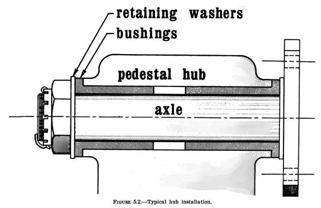
where "W" is the certificated gross weight of the airplane. Skis approved for airplanes of greater gross weight than the airplane on which they are to be installed may be used provided the geometry of the ski is similar to that of a ski previously approved for the airplane (not more than 10 percent difference in width or length of contact surface). This limitation is to assure that the performance of the airplane will not be adversely affected by oversize skis. 64. LANDING GEAR MOMENT REACTIONS. In order to avoid excessive moment reactions on the landing gear and attachment structure, the ski pedestal height must not exceed 130 percent of the axle centerline height with the wheel and tire installed. 65. [RESERVED] Section 2. CONVERSION AND INSTALLATION 66. HUB-AXLE CLEARANCE. The pedestal hub should fit the axle to provide a clearance of 0.005" minimum to 0.020" maximum. Hubs may be bushed to adjust for axle size, using any ferrous or nonferrous metal, hard rubber, or fiber. If rubber or fiber bushings are used, use retaining washers of sufficient size on each side to retain the hub if the bushing should slip or fail. (See figure 5.2.) 67. CRUST-CUTTER CABLES. Crust-cutter cables are optional. However, when operating in severe crust conditions, it is advisable to have this cable installed to prevent the shock cord from being cut if the nose of the ski breaks through the crust while taxiing. 68. CABLE AND SHOCK CORD ATTACHMENT AND ATTACHMENT FITTINGS. Service reports indicate that failure of the ski itself is not a predominant factor in ski failures. Rigging (improper tension and terminal attachments) and cast-type pedestal material failures are predominant. Usually, failures of the safety cable and shock cord attachment fittings occur at the ski end and not at the fuselage end. Do not attach tension cords and safety cables at the same point on the
fuselage fittings. Provide separate means of attaching cables and shock
cords at the forward and aft ends of the skis. Usually, approved skis are
supplied with cables, shock cord, and fittings; however, the following
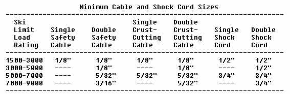
specifications may be used for their fabrication and installations:
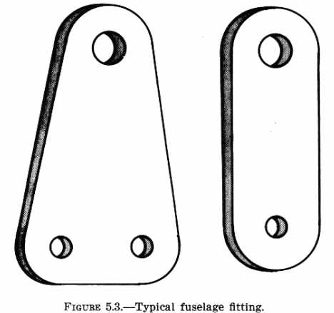
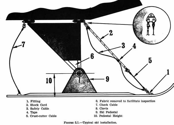
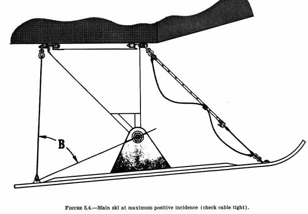
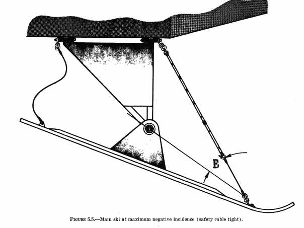
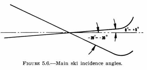
a. Cables. Make the check cable, safety cable, and crust-cutting cable ends by the splice, swage, or nicopress methods; or if adjustable lengths are desired, use cable clamps. Use standard aircraft hardware only. (Hardware used to attach cables must be compatible with cable size.) b. Shock cord ends may be fabricated by any of the following methods: (1) Make a wrapped splice using a proper size rope thimble and No. 9 cotton cord or 0.035" (minimum) safety wire. Attach with clevis or spring steel snap fastener. (DO NOT use cast iron snaps.) (2) Use approved spring-type shock cord end fasteners. c. Fitting Specifications (see figure 5.3) and Installation: (1) Fittings fabricated for 1/8 inch cable or 1/2 inch shock cord shall be at least 0.065" 1025 steel or its equivalent. (2) Fittings fabricated for 5/32 inch cable or 3/4 inch shock cord shall be at least 0.080" 1025 steel or its equivalent. (3) An improperly installed fitting may impose excessive eccentric loads on the fitting and attach bolts and result in failure of the fitting or bolts. 69. PROVISIONS FOR INSPECTION. Aircraft using fabric covered landing gear may have the lower 4 inches of fabric removed to facilitate inspection of the axle attachment area. (See figure 5.1.) 70. [RESERVED] Section 3. RIGGING OF SKIS 71. LOCATION OF ATTACH FITTINGS ON FUSELAGE OR LANDING GEAR. Locate fittings so the shock cord and cable angles are not less than 20° when measured in the vertical plane with the shock absorber in the fully extended position (see angle B, figures 5.4 and 5.5). Note: Do not attach fittings to wing-brace struts, except by special approval (manufacturer or FAA). 72. MAIN SKI INCIDENCE ANGLES. (Aircraft leveled and shock absorbers fully extended.) a. Adjust length of check cable to provide a zero to 5 degree ski incidence
angle (reference figures 5.4 and 5.6).
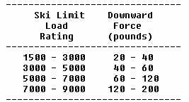
73. TENSION REQUIRED IN MAIN SKI SHOCK CORDS. Apply sufficient shock cord tension to fore end of the skis to prevent
flutter at various airspeeds and attitudes. Because of the various angles
used in attaching shock cord to the skis, shock cord tension cannot be
specified. In most installations the downward force applied at the fore
end of the ski, sufficient to cause the check cable to slacken, should
be approximately as listed below:
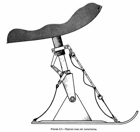
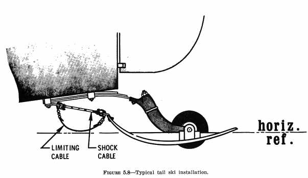
74. NOSE SKI INSTALLATION. The nose ski is installed in the same manner as the main skis (see figure 5.7) except: a. Adjust length of safety cable to provide -5 to -15 degree ski incidence. b. Where it is possible for the nose ski rigging to contact the propeller tips due to vibration, install a 1/4 inch chock cord to hold the rigging out of the propeller arc. 75. TAIL SKI INSTALLATION. a. Use tail skis that have been approved on airplanes of approximately the same weight (within 10 percent) or select as outlined in section 1. Depending upon the type of ski selected, the tail wheel may or may not have to be removed. b. Adjust the length of the limiting cable (reference figure 5.8) to allow the ski to turn approximately 35 degrees either side of the straight forward position with the weight of the airplane resting on the ski. c. The shock cord (reference figure 5.8) must be of a length that will hold the ski in the straightforward position during flight. 76. - 78. [RESERVED] Section 4. OPERATION 79. PERFORMANCE INFORMATION. The following FAA policies concern performance data and operational chock flights for ski installations. a. For aircraft over 6,000 pounds maximum certificated weight, state the following or similar information in the performance information section of the Airplane Flight Manual and obtain FAA approval. (1) Takeoff. Under the most favorable conditions of smooth packed snow at temperatures approximating 32° F, the skiplane takeoff distance is approximately 10 percent greater than that shown for the landplane. NOTE: In estimating takeoff distances for other conditions, caution should be exercised as lower temperatures or other snow conditions will usually increase these distances. (2) Landing. Under the most favorable conditions of smooth packed snow at temperatures approximately 32° F, the skiplane landing distance is approximately 20 percent greater than that shown for the landplane. NOTE: In estimating landing distances for other conditions, caution should be exercised as other temperatures or other snow conditions may either decrease or increase these distances. (3) Climb Performance. In cases where the landing gear is fixed (both landplane and skiplane), where climb requirements are not critical, and the climb reduction is small (30 to 50 feet per minute), the FAA will accept a statement of the approximate reduction in climb performance placed in the performance information section of the Airplane Flight Manual. For larger variations in climb performance, or where the minimum requirements are critical, or where the landing gear of the landplane was retractable, appropriate climb data should be obtained to determine the changes, and new curves, tables, or a note should be incorporated in the Airplane Flight Manual. b. For aircraft of 6,000 pounds or less maximum certificated weight, make the information in 79a available to the pilot in the form of placards, markings, manuals, or any combination thereof. 80. FLIGHT AND HANDLING OPERATIONAL CHECKS. Accomplish an operational check which includes more than one landing to determine the ground handling characteristics as well as takeoff and landing characteristics. Take note of ski angles during tail high and tail low landings to avoid having the ski dig in or fail from localized stress. Determine there is sufficient ground control to satisfactorily complete a landing run with a turnoff at slow speed in cases where brakes are not provided. In flight, the ski should ride steady with no unusual drag and produce no unsatisfactory flight characteristics. Enter a notation of these checks in the aircraft records. 81. INTERCHANGING OF SKIS AND WHEELS. After the initial installation, removing the skis and reinstalling the wheels or vice versa may be considered a preventive maintenance operation when no weight-and-balance computation is involved. 82. - 85. [RESERVED] |
||||||
| ©AvStop Online Magazine Contact Us Return Home |
