
![]()
![]()
|
|
|
|
Chapter 6. Oxygen System Installations In Nonpressurized Aircraft
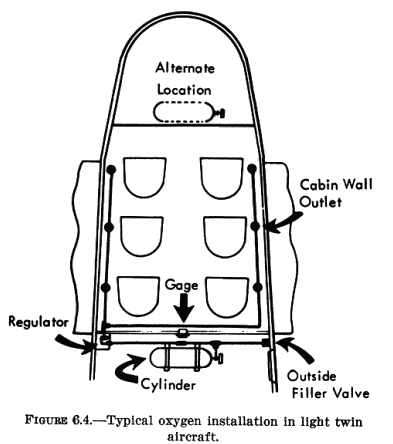
(3) Use 5/16 inch O.D. aluminum alloy tubing after the pressure reducer (low pressure side). (4) Use flexible connections specifically designed for oxygen between all points having relative or differential motion. b. Valves. A slow opening valve is used as a cylinder shutoff valve, or system shutoff valve. Rapid opening and the subsequent sudden and fast discharge of oxygen into the system can cause dangerous heating which could result in fire or explosion of combustibles within the system. c. Regulators. The cylinder or system pressure is reduced to the individual cabin outlets by means of a pressure reducing regulator which can be manually or automatically controlled. d. Types of Regulators. The four basic types of oxygen systems, classified according to the type of regulator employed, are: (1) Demand type.
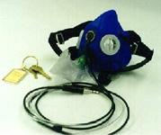
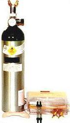
e. Flow Indicators. (1) A pith ball flow indicator, vane, wheel anemometer, or lateral pressure indicator which fluctuates with changes in flow or any other satisfactory flow indicator may be used in a continuous flow-type system. (2) An Air Force - Navy flow indicator or equivalent may be used in a diluter demand type system. Each flow indicator should give positive indication when oxygen flow is occurring. f. Relief Valve. (1) A relief valve is installed in low pressure systems to safely relieve excessive pressure, such as caused by overcharging. (2) A relief valve is installed in high pressure oxygen systems to safely relieve excessive pressure, such as caused by heating. g. Gauge. Provide a pressure gauge to show the amount of oxygen in the cylinder. h. Masks. Only masks designed for the particular system should be used. 87. INSTALLATION. Oxygen systems present a hazard. Therefore, follow the precautions and practices listed below: a. Remove oil, grease (including lip salves, hair oil, etc.), and dirt from hands, clothing, and tools before working with oxygen equipment. b. Prior to cutting the upholstery, check the intended route of the system. Make sure that all system components are kept completely free of oil or grease during installation and locate components so they will not contact or become contaminated by oil or hydraulic lines. c. Keep open ends of cleaned and dried tubing capped or plugged at all times, except during attachment or detachment of parts. Do NOT use tape, rags, or paper. d. Clean all lines and fittings which have not been cleaned and sealed by one of the following methods: (1) A vapor degreasing method with stabilized trichloroethylene conforming to Specification MIL-T-7003 or carbon tetrachloride. Blow tubing clean and dry with a stream of clean, dried, water pumped air, or dry nitrogen (water vapor content of less than 0.005 milligrams per liter of gas at 70° F and 760 millimeters of mercury pressure). (2) Flush with naphtha conforming to Specification TT-N-95; blow clean and dry of all solvent with water pumped air; flush with anti-icing fluid conforming to Specification MIL-F-5566 or anhydrous ethyl alcohol; rinse thoroughly with fresh water; and dry thoroughly with a stream of clean, dried, water pumped air, or by heating at a temperature of 250° to 300° F for one-half hour. (3) Flush with hot inhibited alkaline cleaner until free from oil and grease; rinse thoroughly with fresh water; and dry thoroughly with a stream of clean, dried, water pumped air, or by heating at a temperature of 250° to 300° F for one-half hour. e. Install lines, fittings, and equipment above and at least 6 inches away from fuel, oil, and hydraulic systems. Use deflector plates where necessary to keep hydraulic fluids away from the lines, fittings, and equipment. f. Allow at least a 2 inch clearance between the plumbing and any flexible control cable or other flexible moving parts of the aircraft. Provide at least 1/2 inch clearance between the plumbing and any rigid control tubes or other rigid moving parts of the aircraft. g. Allow a 6 inch separation between the plumbing and the flight and engine control cables, and electrical lines. When electrical conduit is used, this separation between the plumbing and conduit may be reduced to 2 inches. h. Route the oxygen system tubing, fittings, and equipment away from hot ducts and equipment. Insulate or provide space between these items to prevent heating the oxygen system. i. Mount all plumbing in a manner which prevents vibration and chafing. Support 3/16 inch O.D. copper line each 24 inches and 3/16 inch O.D. aluminum each 36 inches with cushioned loop-type line support clamps (AN-742) or equivalent. j. Locate the oxygen supply valve (control valve) so as to allow its operation by the pilot during flight. The cylinder shutoff valve may be used as the supply control valve, if it is operable from the pilot's seat. Manifold plug-in type outlets, which are incorporated in automatic systems, may be considered as oxygen supply valves since the pilot can control the flow of oxygen by engaging and disengaging the plug-in type oxygen mask. NOTE: Locate the oxygen shutoff valve on or as close as practicable to the cylinder to prevent loss of oxygen due to leakage in the system. 88. LOCATION AND MOUNTING. Determine the weight factor and c.g. limits for the installation prior to commencing the installation. a. Mount the cylinder in the baggage compartment or other suitable location in such a position that the shutoff valve is readily accessible. If possible, provide access to this valve from inside the cabin so that it may be turned on in flight in the event that it was not opened prior to takeoff. b. Fasten the cylinder brackets securely to the aircraft, preferably to a frame member or floorboard using AN bolts with fiber or similar locking nuts. Add sufficient plates, gussets, stringers, crossbracing, or other reinforcements, where necessary, to provide a mounting that will withstand the inertia forces stipulated in chapter 1 of this handbook. c. When cylinders are located where they may be damaged by baggage or stored materials, protect them by a suitable guard or covering. d. Provide at least 1/2 inch of clear airspace between any cylinder and a firewall or shroud isolating a designated fire zone. e. Mount the regulator close to the cylinder to avoid long high pressure lines. f. Store the masks in such a way that there will be a minimum delay in removing and putting them into use. 89. THREAD COMPOUND. Use antiseize or thread sealing compound conforming to Specification MIL-T-5542B, or equivalent. a. Do not use compound on aluminum alloy flared tube fittings having straight threads. Proper flaring and tightening should be sufficient to make a flared tube connection leakproof. b. Treat all male tapered pipe threads with antiseize and sealing compound (MIL-T-5542B, or tetrafluoroethylene tape MIL-T-27730), or equivalent. c. Apply the compound in accordance with the manufacturer's recommendation. Make sure that the compounds are carefully and sparingly applied only to male threads, coating the first three threads from the end of the fitting. Do not use compound on the coupling sleeves or on the outside of the tube flares. 90. FUNCTIONAL TEST. Before inspection plates, cover plates, or upholstering are replaced, make a system check including at least the following: a. Open cylinder valve slowly and observe the pressure gauge. b. Open supply valve and remove one of the mask tubes and bayonet fittings from one of the masks in the kit. Plug the bayonet into each of the oxygen outlets. A small flow should be noted from each of the outlets. This can be detected by holding the tube to the lips while the bayonet is plugged into an outlet. c. Check the complete system for leaks. This can be done with a soap solution made only from a mild (castile) soap or by leak detector solution supplied by the oxygen equipment manufacturer. d. If leaks are found, close the cylinder shutoff valve and reduce the pressure in the system by plugging a mask tube into one of the outlets or by carefully loosening one of the connections in the system. When the pressure has been reduced to zero, make the necessary repairs. Repeat the procedure in 90c until no leaks are found in the system. Caution: Never tighten oxygen system fittings with oxygen pressure applied. e. Test each outlet for leaks at the point where the mask tube plugs in. This can be done by drawing a soap bubble over each of the outlets. Use the solution sparingly to prevent clogging the outlet by soap. Remove all residue to prevent accumulation of dirt. f. Examine the system to determine that the flow of oxygen through each outlet is at least equal to the minimum required by the pertinent requirements at all altitudes at which the aircraft is to be operated. This can be accomplished by one of the following methods: (1) In a continuous flow system when the calibration (inlet pressure vs. flow) of the orifices used at the plug-in outlets is known, the pressure in the low pressure distribution line can be measured at the point which is subject to the greatest pressure drop. Do this with oxygen flowing from all outlets. The pressure thus measured should indicate a flow equal to or greater than the minimum flow required. (2) In lieu of the above procedure, the flow of oxygen, through the outlet which is subject to the greatest pressure drop, may be measured with all other outlets open. Gas meters, rotometers, or other suitable means may be used to measure flows. (3) The measurement of oxygen flow in a continuous flow system which uses a manually adjusted regulator can be accomplished at sea level. However, in a continuous flow system which uses an automatic-type regulator, it may be necessary to check the flow at maximum altitude which will be encountered during the normal operation of the aircraft. The manufacturer of the particular continuous flow regulator used should be able to furnish data on the operating characteristics of the regulator from which it can be determined whether a flight check is necessary. (4) The checking of the amount of flow through the various outlets in a diluter demand or straight demand system is not necessary since the flow characteristics of the particular regulator being used may be obtained from the manufacturer of the regulator. However, in such systems the availability of oxygen to each regulator should be checked by turning the lever of the diluter demand regulator to the "100 percent oxygen" position and inhaling through the tube via the mask to determine whether the regulator valve and the flow indicator are operating. g. Provide one of the following acceptable means or equivalent to indicate oxygen flow to each user by: (1) Listening for audible indication of oxygen flow. (2) Watching for inflation of the rebreather or reservoir bag. (3) Installation of a flow indicator. 91. OPERATING INSTRUCTIONS. Provide instructions appropriate to the type of system and masks installed
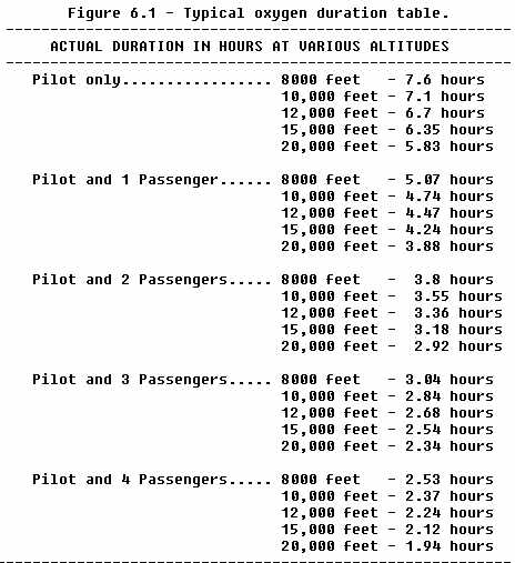
for the pilot on placards. Include in these instructions a graph or a table
which will show the duration of the oxygen supply for the various cylinder
pressures and pressure altitudes.
NOTE: The above duration time is based on a fully charged 48 cubic
foot cylinder. For duration using 63 cubic foot
92. - 95. [RESERVED] |
|||||
| ©AvStop Online Magazine Contact Us Return Home |
