
![]()
![]()
|
|
|
|
Chapter 7. Rotorcraft External-Load Device Installations
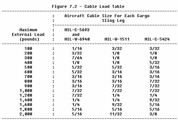
98. LOCATION OF CARGO RELEASE IN RELATION TO THE ROTORCRAFT'S C.G. LIMITS. a. An ideal location of the cargo release would be one that allows the line of action to pass through the rotorcraft's center of gravity at all times. (See figure 7.1, illustration A.) However, with most cargo sling installations, this ideal situation is realized only when the line of action is vertical or near vertical and through the rotorcraft's c.g. (See figure 7.1, illustration B.) b. Whenever the line of action does not pass through the rotorcraft's c.g. due to the attachment method used, acceleration forces, or aerodynamic forces, the rotorcraft-load combined center of gravity will shift from the rotorcraft's c.g. position. Depending upon the factors involved, the shift may occur along either or both the longitudinal or lateral axes. The amount of shift is dependent upon the force applied (F) and the length of the arm of the line of action. Their product (F x Arm) yields a moment which can be used to determine the rotorcraft-load combined center of gravity. (See figure 7.1, illustration C.) If the rotorcraft-load center of gravity is allowed to shift beyond the rotorcraft's approved center of gravity limits, the rotorcraft may become violently uncontrollable. c. Thus, any attachment method or location which will decrease the length of the arm will reduce the distance that the combined center of gravity will shift for a given load (F) and line of action angle. (See figure 7.1, illustration D.) 99. MAXIMUM EXTERNAL LOAD. The maximum external load (including the weight of the cargo sling) for which authorization is requested may not exceed the rated capacity of the quick release device. 100. STATIC TEST. The cargo sling installation must be able to withstand the static load required by FAR 133.43 (a). Conduct the test as outlined in Chapter 1 of this advisory circular. If required during the test, supports may be placed at the landing gear to airframe attach fittings to prevent detrimental deformation of the landing gear due to the weight of the aircraft. 101. SLING LEG ANGLES OF CABLE SUPPORTED SLINGS. The optimum sling leg angle (measured from the horizontal) is 45 to 60 degrees. Minimum tension in a sling leg occurs with a sling leg angle of 90 degrees, and the tension approaches infinity as the angle approaches zero. Thus, larger sling leg angles are desirable from a standpoint of cable strength requirements. Slings should not be attached in such a manner as to provide sling leg angles of less than 30 degrees. 102. MINIMUM SLING LEG CABLE STRENGTH. An analysis which considered the effects of 30 degree sling angles showed that the minimum cable strength design factor required would be 2.5 times the maximum external load for each leg regardless of the number of legs. Although this is the minimum strength required by Part 133, it may be desirable to double this value to allow for deterioration of the sling leg cables in service. This will result in a cable strength equal to 5 times the maximum external load. Example: Maximum external load 850 pounds
A 3/16 inch, nonflexible 19 wire cable (MIL-W-6940) provides a satisfactory
cable strength. See figure 4.1, chapter 4, of AC
43.13-1A for a table of breaking strength of steel cable. For convenience,
the cable sizes desired for various loads have been calculated and are
tabulated in figure 7.2 based on a factor of 5:
103. SLING INSTALLATION. Attach the cargo sling to landing gear members or other structure capable
of supporting the loads to be carried. Install
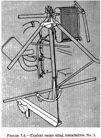
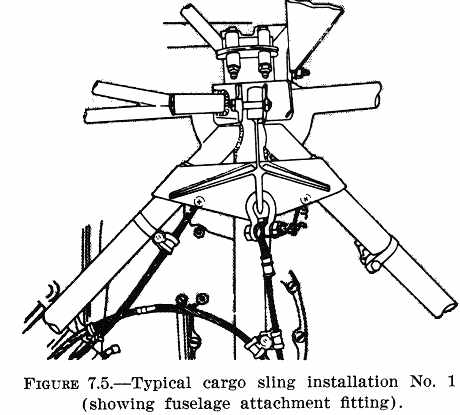
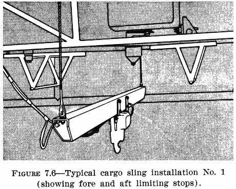
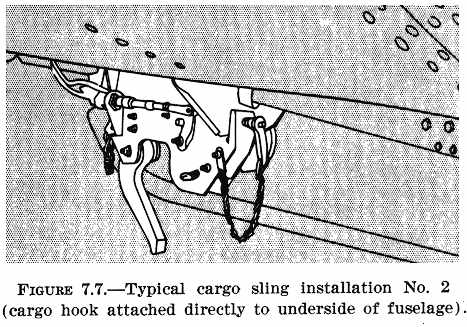
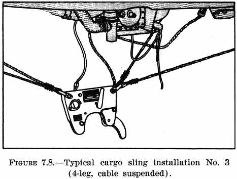
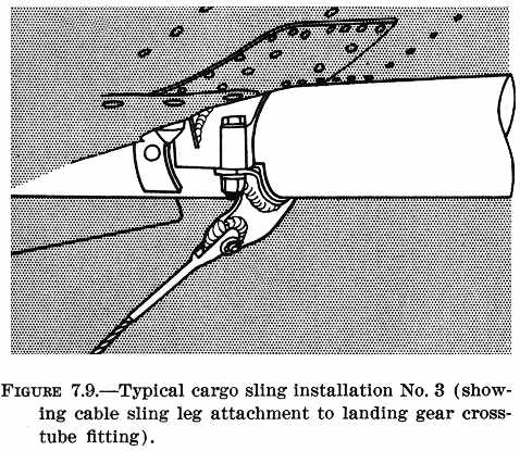
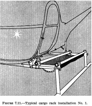
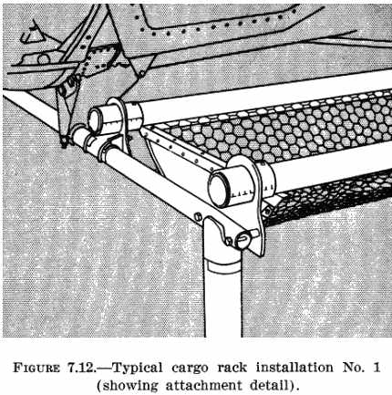
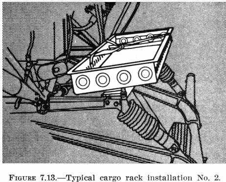
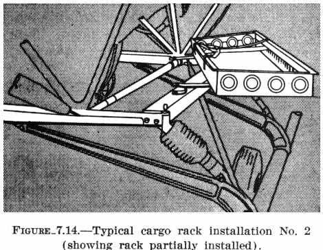
Some cargo release devices are provided with a fitting to permit installation of a guideline to assist in fully automatic engagement of the load target ring or load bridle. Secure the guideline to the quick release device with a shear pin of a definite known value which will shear if a load becomes entangled on or over the guideline. Provision should also be made for cable supported slings to be drawn up against the fuselage into a stowage position to prevent striking or dragging the release on the ground when not in use. 104. INSTALLATION OF RELEASE CONTROLS. See figure 7.3 for typical wiring diagram of the electrical controls. a. Install a cargo release master switch, readily accessible to the pilot, to provide a means of deactivating the release circuit. The power for the electrical release circuit should originate at the primary bus. The "auto" position of the release master switch on some cargo release units provides for automatic release when the load contacts the ground and the load on the release is reduced to a preset value. b. Install the cargo release switch on one of the pilot's primary controls. It is usually installed on the cyclic stick to allow the pilot to release the load with minimum distraction after maneuvering the load into the release position. c. Install the emergency manual release control in a suitable position that is readily accessible to the pilot or other crewmember. Allow sufficient slack in the control cable to permit complete cargo movement without tripping the cargo release. d. The manual ground release handle, a feature of some cargo release units, permits opening of the cargo release by ground personnel. e. Label or placard all release controls as to function and operation. 105. FUNCTIONAL TEST. Test the release action of each release control of the quick release device with various loads up to and including the maximum external load. This may be done in a test fixture or while installed on the rotorcraft, if the necessary load can be applied. If the quick release device incorporates an automatic release, the unit should not release the load when the master switch is placed in the "automatic" position until the load on the device is reduced to the preset value, usually 80 to 120 pounds. {See Figure 7.4.} 106. SUPPLEMENTAL FLIGHT INFORMATION. The aircraft may not be used in Part 133 external-load operations until a Rotorcraft-Load Combination Flight Manual is prepared in accordance with section 133.47 of that Part. {See Figure 7.5.} {See Figure 7.6.} {See Figure 7.7.} {See Figure 7.8.} {See Figure 7.9.} {See Figure 7.10.} 107. - 110. [RESERVED] Section 2. CARGO RACKS 111. GENERAL. This section contains structural and design information for the fabrication and installation of a cargo rack used as an external-load attaching means for a Class A rotorcraft-load combination operation under FAR Part 133. 112. FABRICATION OF CARGO RACKS. The type of construction and method of attachment depend upon the material to be used and the configuration of the rotorcraft involved. Illustrations of typical construction and installation methods are shown in figures 7.11 - 7.15. {See Figure 7.12} {See Figure 7.13} {See Figure 7.14} 113. STATIC TEST. The cargo rack installation must be able to withstand the static test load required by FAR 133.43(a). Conduct the test as outlined in chapter 1 of this handbook. 114. SUPPLEMENTAL FLIGHT INFORMATION. The aircraft may not be used in Part 133 external-load operations until a rotorcraft-load combination flight manual is prepared in accordance with section 133.47 of that Part. 115. - 120. [RESERVED] |
||||
| ©AvStop Online Magazine Contact Us Return Home |

