
![]()
![]()
|
|
|
|
Chapter 8. Glider And Banner Tow-Hitch Installations
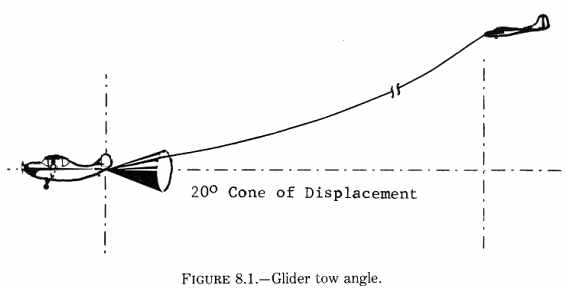
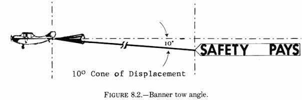
a. Glider tow hitches. Protection for the towplane is provided by requiring use of a towline assembly which will break prior to structural damage occurring to the towplane. The normal tow load of a glider rarely exceeds 80 percent of the weight of the glider. Therefore, the towline assembly design load for a 1,000 pound glider could be estimated at 800 pounds. By multiplying the estimated design load by 1.5 (to provide a safety margin), we arrive at a limit load value of 1,200 pounds. The 1,200 pound limit load value is used in static testing or analysis procedures per paragraph 127 of this handbook to prove the strength of the tow hook installation. When the hook and structure have been proven to withstand the limit load, then the MAXIMUM breaking strength of the towline assembly is established at the design load of 800 pounds. Thus, the towline will break well before structural damage will occur to the towplane. {See Figure 8.1.} Another approach can be applied if the limit load carrying capabilities of a tow hook and fuselage are known. In this case, the known load value can be divided by 1.5 to arrive at the design load capabilities if the tow hook and fuselage limit loads are known to be 1,800 pounds. By dividing by 1.5 (1800 divided by 1.5 = 1,200) we arrive at a design load value of 1,200 pounds. Thus, the maximum breaking strength of the towline assembly is established at 1,200 pounds and provides protection for the towplane. Thus, in considering tow hook installations, one may establish maximum towline breaking strength by: (1) Dividing the known limit load capabilities of the fuselage and two hook installation by 1.5; or (2) Knowing the design load needs of the towline assembly and multiplying by 1.5 to arrive at a limit load. Then by analysis or static testing, determine that the hook and fuselage are capable of withstanding that limit load. b. Banner tow hitches. Install the hitch to support a limit load equal to at least two times the operating weight of the banner. 127. STRUCTURAL TESTING. Adequacy of the aircraft structure to withstand the required loads can be determined by either static test or structural analysis. a. Static testing. When using static tests to verify structural strength, subject the tow hitch to the limit load (per paragraph 126 a or b) in a rearward direction within the appropriate cone of displacement per figure 8.2. Testing to be done in accordance with the procedures of Chapter 1, paragraph 3, of this handbook. b. Structural analysis. If the local fuselage structure is not substantiated by static test for the proposed tow load, using a method that experience has shown to be reliable, subject the fuselage to engineering analysis to determine that the local structure is adequate. Use a fitting factor of 1.15 or greater in the loads for this analysis. 128. ATTACHMENT POINTS. Tow-hitch mechanisms are characteristically attached to, or at, tiedown points or tailwheel brackets on the airframe where the inherent load bearing qualities can be adapted to towing loads. Keep the length of the hitch assembly arm from the airframe attachment point to the tow hook to a minimum as the loads on the attachment bolts are multiplied by increases in the moment arm. 129. ANGLES OF TOW. Tests should be conducted on the system at various tow angles to insure that: a. There is no interference with the tailwheel or adjacent structure.
130. PLACARDS. A placard should be installed in a conspicuous place in the cockpit to notify the pilot of the structural design limits of the tow system. The following are examples of placards to be installed: a. For glider tow - "Glider towline assembly breaking strength not to
exceed ____*____ pounds."
* Value established per paragraph 126 a (1) or (2).
131. WEIGHT AND BALANCE. In most cases, the weight of the tow-hitch assembly will affect the fully loaded aft c.g. location. To assure that the possibility of an adverse effect caused by the installation has not been ignored, enter all pertinent computations in the aircraft weight & balance records. (In accordance with the provisions contained in FAR 43.5(a)(4).) 132. TOW RELEASE MECHANISM. a. Release lever. A placard indicating the direction of operation should be installed
to allay the possibility of confusion or inadvertent operation,
(1) Convenience in operation.
(a) Wear and abrasion during normal operation.
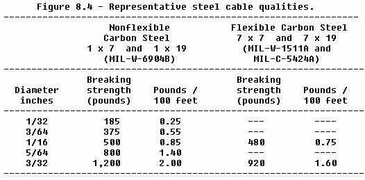
b. Test of the release. A test of the release and hook for proper operation through all angles of critical loading should be made using the design load for the glider or banner. c. Release cable. Representative size and strength characteristics of steel release cable
are as shown in figure 8.4; however, it is recommended that all internally
installed release cables be 1/16 inch or larger.
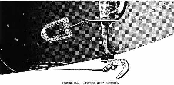
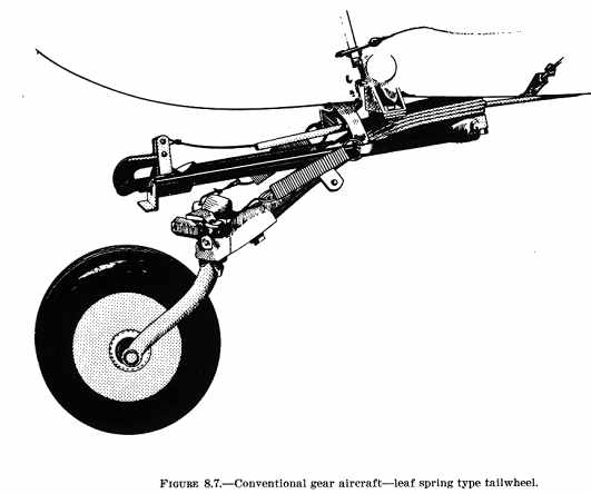
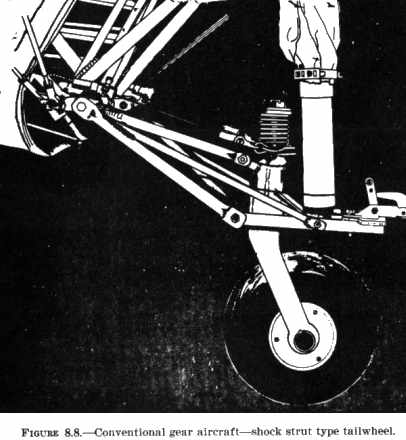
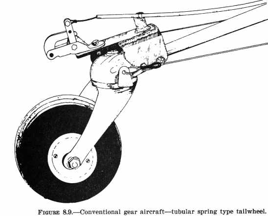
133. [DELETED] Change 1 (DELETED) - Change 2 {See Figure 8.6.} {See Figure 8.7.} {See Figure 8.8.} {See Figure 8.9.} 134. - 145. [RESERVED] |
||||
| ©AvStop Online Magazine Contact Us Return Home |

