
![]()
![]()
|
|
|
|
Chapter 9. Shoulder
Harness Installations On Aircraft
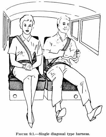
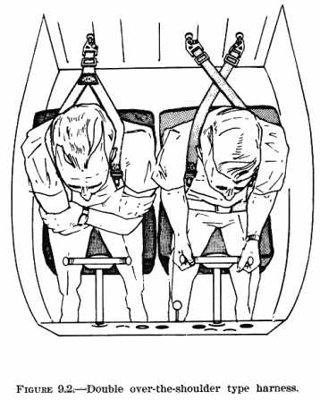
The human body has the inherent capability of withstanding decelerations of 20 g's for time periods of up to 200 milliseconds (0.2 second) without injury. Experience with aircraft used in agricultural and military operations shows that even in such unusual operations a high rate of survival in crashes is achieved when a restraint system is designed on the order of 20 g to 25 g deceleration loads. In view of the foregoing, persons installing a shoulder harness may wish to use a restraint system designed to withstand 20 g to 25 g loads. In addition, seat belts and seat belt anchorages designed to these load limits may be used. 147. TYPES OF RESTRAINT SYSTEMS. There are two generalized types of shoulder harnesses currently in use. They are the single diagonal type harness and the double over-the-shoulder type harness. The over-the-shoulder harness may utilize either two independent attach points, or join in a "Y" configuration and attach at a single point. (See figures 9.1 and 9.2) In all cases, however, the original safety belt or a combination harness utilizing a lap belt must be used in the installation. 148. ADVANTAGES OF DIFFERENT HARNESS TYPES. The single diagonal chest strap in combination with a lap belt is the simplest harness system and works effectively for longitudinal decelerations. However, during side decelerations, an occupant in this type harness has a tendency to slip out and away from the chest strap even when it fits snugly. The double over-the-shoulder type harness works well for both longitudinal and side decelerations. 149. MOUNTING CONFIGURATIONS. The type of shoulder restraint configuration acceptable for installation is dependent upon the attachments available in each individual aircraft. Basic harness mounting configurations are: a. Seat mounted.
(1) Side
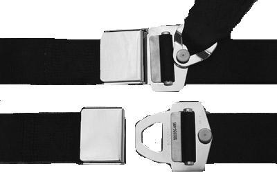
150. STANDARDS. At the present time, there is a lack of standards for materials acceptable for use in shoulder harnesses. Until such time as a TSO is developed for shoulder harnesses, standards established in TSO-C22f pertaining to the materials and testing of safety belts may be accepted for this purpose. 151. MATERIALS. a. Webbing. Synthetic materials, such as nylon and dacron, may be used for shoulder harness webbing. It is recommended that the webbing of the shoulder harness be the same as that of the lap belt to avoid problems in cleaning, staggered replacement of harness components due to wear or age, etc. b. Fittings. Use hardware that: (1) Conforms to an acceptable standard such as AN, NAS, TSO, or MIL-SPEC.
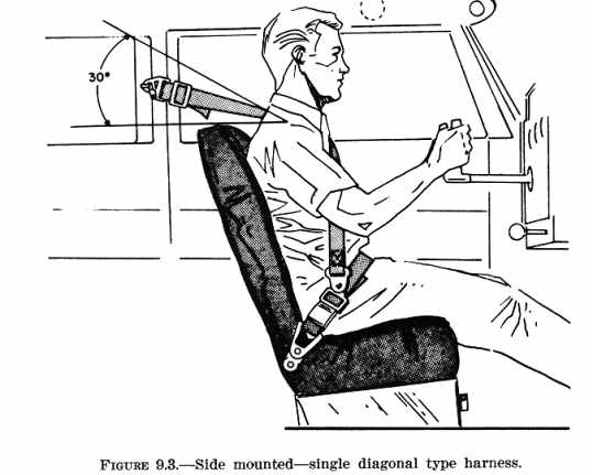
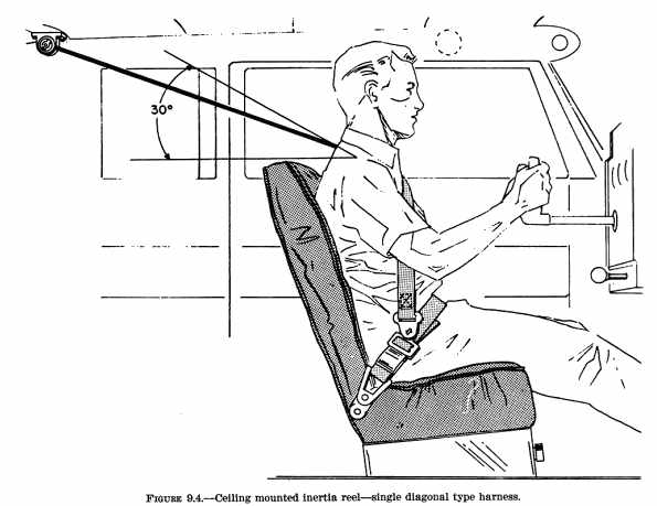
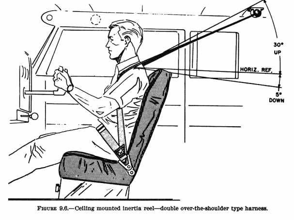
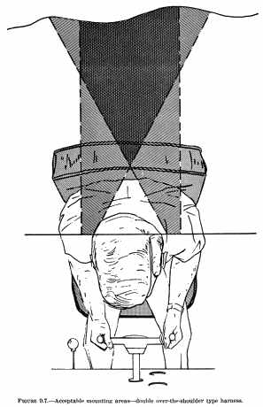
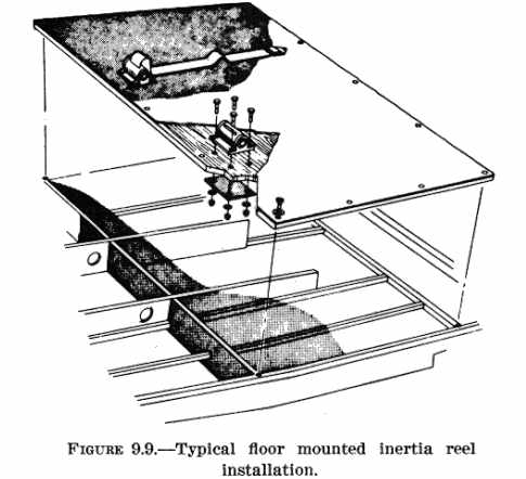
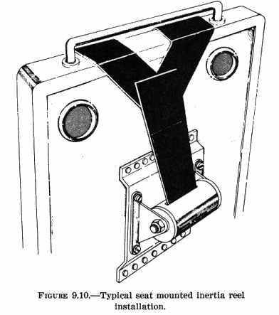
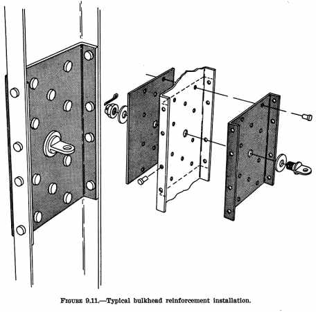
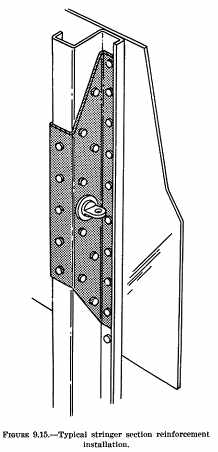
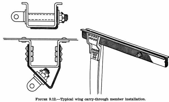
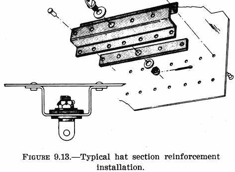
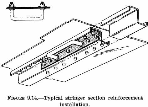
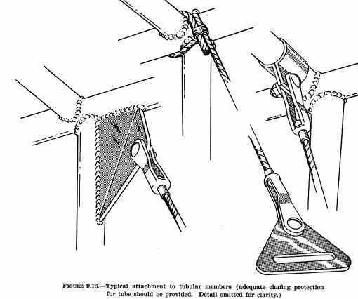
c. Inertia Reels. The function of the inertia reel is to lock and restrain the occupant in a crash yet provide the ability for normal movement without restrictions. In addition, automatic rewinding of any slack assures that the harness is always snug, which results in a more comfortable restraint system. Self-contained inertia reel units may be mounted at readily accessible locations and will generally operate effectively in any attitude. Their use in a body restraint system is satisfactory if mounted in accordance with acceptable methods, techniques, and practices, and will meet static strength requirements equal to those outlined in FAR 23.1413. Check the reel itself for the following operational hazards: (1) Inadvertent Lockup. If the inertia mechanism is set at a low "g" setting, unwanted lockup, or binding, of the system may occur. A reel lockup range between 0.9 and 2.5 "g" is acceptable. (2) Improper Webbing Length. Install adequate webbing on the takeup reel to allow the occupant to reach all necessary switches and controls in the cockpit. Any additional webbing will result in decreasing the reel spring "takeup" tension exerted on the shoulder. (3) Incorrect Belt Opening Alignment. Position the reel so that the belt opening is aligned in the direction of loading. This will prevent the belt from rubbing and fraying due to normal usage. 152. - 155. [RESERVED] Section 2. EFFECTIVE RESTRAINT ANGLES 156. RELATIONSHIP OF THE HARNESS ASSEMBLY TO THE OCCUPANT. Most restraint systems are designed so that each belt section maintains a certain relationship to the body. The attachment end of a restraint belt must maintain a relative angle and spacing to the head and neck surfaces as it passes over the shoulder and away from the body. This angle must provide sufficient freedom to assure normal body movements of the seated occupant without neck contact or interfering with vision. 157. ATTACHMENT AREAS FOR SHOULDER HARNESS. Effective attachment areas for the various types of shoulder harnesses are defined as angles formed by the attachment ends. Assure that when installing a harness for one seat that in a crash, a passenger to the rear would not sustain head impact injuries on the harness or its attach point. a. Single Diagonal Type Harness. The optimum rearward attachment area for this type of harness is within an angle of 30 degrees above the horizontal measured from the midpoint on the occupant's shoulder as shown in figures 9.3 and 9.4. Belt attachments should be located to the rear and outboard of the shoulder. This mounting area is shown in figure 9.5. (1) Attachment points inboard of this area would permit the harness to impinge on the neck and could result in neck injury during crash impact. In addition, the constant rubbing of the strap on the neck would be uncomfortable and, as a result, act as a distraction to the safe operation of the aircraft. Attachment points forward of this area would reduce the effectiveness of the harness, due to a lack of contact between the harness and the upper torso of the occupant. In addition, a shoulder strap attached forward of the shoulder midpoint could obstruct vision and create a potential safety hazard. (2) The harness should be kept snug as any decrease in the distance between the occupant's head and the forward cabin structure increases the opportunities for head impact injuries. Also, the chances for twisting out of the harness are significantly increased. b. Double Over-the-Shoulder Type Harness. If this type of harness is intended to be mounted either directly rearward or to the ceiling, mount it within the 30 degree vertical angle as shown in figure 9.6. Because of the limited number of rearward shoulder harness attachment points in many aircraft, a 5 degree angle below the horizontal is also considered acceptable. Shoulder harness attach areas as viewed from above are shown in figure 9.7. These mounting areas may be used for either the independent or the "Y" type belts. The outboard limit is established to prevent the belt section from slipping off the shoulder, and the maximum inboard angle is limited to a point which will prevent impingement on the neck surface. 158. AREA AND ANGLE DEVIATIONS. While the areas and angles given in the above paragraphs are intended to assist in the selection of attachment points, they should be considered as the optimum and not be interpreted as being mandatory. Area and/or angle deviations could result in a decrease in the overall efficiency of the restraint system; however, they may be necessary in order to permit a harness installation in an aircraft which otherwise could not be accomplished. It is probable that other compromises may be necessary when adapting a specific restraint system to an aircraft in order to fit a body of average dimensions. These compromises, however, should be permitted only when they are compatible with proper restraint functions. 159. - 160. [RESERVED] Section 3. ATTACHMENT METHODS 161. STRUCTURAL ATTACHMENTS. For best results, the restraint system should be anchored to the primary aircraft structure. Design the structural attachment to spread the suddenly applied impact loads over as large an area of the structure as possible. The shoulder harness may be attached to selected secondary members which will deform slowly or collapse at a limited rate. This will assist in dissipating the high impact "g" loads to a level tolerable to the human body. However, the possibility of secondary members collapsing and making it difficult for an occupant to extract himself from the harness should not be overlooked. 162. FLOOR AND SEAT ATTACHMENTS. The double over-the-shoulder type harness shown in figure 9.8 may be used with either floor or seat mounting points, and typical installation methods are illustrated in figures 9.9 and 9.10. Two prerequisites necessary to ensure an effective restraint system are: a. The seat structure and its anchorages should be capable of withstanding the additional "g" loads imposed by the restrained occupant during an abrupt deceleration. This capability may be determined by static testing in accordance with FAR 23.785, 25.785, 27.785, or 29.785, as appropriate; or, by securing a statement attesting this adequacy from the airframe manufacturer's engineering department. b. The level of the seat back should at least be equal to the shoulder height of the seated occupant. This will reduce the inherent downward impact loads which would otherwise impart compressive forces on the occupant's torso. Seats which utilize a fold-over type of seat back must have some type of locking mechanism so that the seat can support the loads without allowing the occupant to move forward. The lock should be of a type which has a quick release to allow rear seat occupants to rapidly evacuate the aircraft. This type of installation should only be considered if other means of attachment are not available since making a folding seat rigid greatly reduces the protection afforded a passenger to the rear. When a folding seat is provided with a lock, the passenger to the rear should also be provided a shoulder restraint system, or, the back of the forward seat should be provided with sufficient absorptive material to adequately compensate for the added rigidity. Also, the change in load distribution due to the loads being applied to the seat back may require reinforcing the seat and/or belt anchorages to meet airworthiness requirements. 163. AIRFRAME ATTACHMENTS. The method used for the attachment of shoulder harness anchorages is dependent upon the construction features of the aircraft involved. a. Monocoque/Semimonocoque Type Constructions. Illustrations of typical aircraft members and installation methods are shown in figures 9.11 through 9.15. {See Figure 9.12} {See Figure 9.13} {See Figure 9.14} b. Tube Type Construction. Various typical methods of attaching shoulder harness anchorages are shown in figure 9.16. When aircraft cable is used as a component in a shoulder harness anchorages, swage the cable terminals in accordance with the procedures contained in chapter 4 of AC 43.13-1A, "Acceptable Methods, Techniques, and Practices - Aircraft Inspection and Repairs." 164. STRUCTURAL REPAIR KITS. In many instances, structural repair kits are available from the aircraft manufacturer. While these kits are primarily intended for use in repairing defective or damaged structure, they may also be used as a reinforcement for shoulder harness attach fittings. 165. FLEXIBLE ATTACHMENTS. Various aircraft are designed so that fuselage members and/or skin will flex or "work." This type of structure should not be heavily reinforced for the purpose of attaching shoulder harnesses as this would defeat the design purpose. In cases such as these, use a localized reinforcement, such as shown in figure 9.15, at the attachment point. This will allow the fuselage to flex while still maintaining a collapsible structure to absorb the loads encountered in a crash. 166. SIMPLIFIED INSTALLATION CRITERIA. To encourage the addition of shoulder restraints to existing aircraft with a minimum of testing and engineering necessary, yet provide a satisfactory restraint, the following general conditions will be acceptable. a. Utilize the original seat belt attachments and either the original
or a new belt provided with shoulder harness fittings.
167. ENGINEERING APPROVAL. Installations which involve cutting or drilling of critical fuselage members or skin of pressurized aircraft will usually require engineering evaluation. For this reason it may be desirable to contact the airframe manufacturer to obtain his recommendations. 168. - 175. [RESERVED] |
||
| ©AvStop Online Magazine Contact Us Return Home |
