
CHAPTER 8. MOORING, LIGHTING, MARKING, AND FUELING
49. ANCHORS.
a. Background. Anchors vary in weight and shape, depending on intended use and bottom conditions. Normal bottoms such as sand, clay, or similar materials require anchors that will "dig in." Mushroom or large base area anchors that will not sink excessively, should be used for soft mud and silt bottoms. For shale, smooth rock or other hard bottoms, a much heavier anchor is required because the weight of the anchor is the principal holding factor. A 5 to 10 pound (2.5 to 4.5 kg) cast iron or steel boat anchor will be satisfactory, under normal conditions, for a temporary or emergency aircraft mooring. These anchors can also be used to secure temporary night lighting buoys or floating lighting devices.
b. Weight. Permanent marker or lighting buoy anchors should not weigh less than 250 pounds (100 kg) when submerged. Small aircraft mooring buoy anchors should not weigh less than 600 pounds (275 kg) when submerged and should not roll on the bottom. An excellent mooring anchor for aircraft of gross weights up to 15,000 pounds (6 800 kg) can be made from two large steel drums or wooden barrels filled with concrete and connected with heavy 2 to 3 inch (5 to 7.5 cm) diameter iron pipe. This anchor has a gross weight of approximately 2,200 pounds (1 000 kg) and a submerged weight of about 1,320 pounds (600 kg). A single barrel anchor constructed as above will be satisfactory for anchoring small aircraft. Three drums may be needed for large aircraft. Filled concrete blocks tied together with reinforcing rods will also make a satisfactory anchor.
50. ANCHOR LINES.
a. Strength. The strength of an anchor line is based on the safe working load being equal to or greater than the gross weight of the anchor. Under most wind and water conditions, .25 inch (6.5 mm) wire rope or chain will be strong enough for mooring aircraft up to 3,000 pounds (1 360 kg) gross weight, and .50 inch (12.5 mm) anchor chains or wire rope will be satisfactory for mooring aircraft up to 15,000 pounds (6 800 kg) gross weight.
b. Effect of Water. Mooring lines of the size indicated will remain serviceable for several years in fresh water. In salt or brackish waters, due to the rapid deterioration of metals, the minimum size should be increased by 1/8-inch (3 mm) unless stainless steel rope is used. A practical application is to attach the anchor line to the end of a heavy chain. This arrangement reduces the strain and shock on the aircraft when riding in rough water or heavy swells. Engineering handbooks give weight and strength characteristics of wire rope and chain and are useful for determining anchor line sizes.
c. Metal Fittings. Copper or bronze fittings should not be in contact with steel fittings or lines. Without insulation, electrolysis takes place, and the metal corrodes. Galvanized screw or pin shackles are recommended at the buoy, thus allowing the buoy to rotate on the anchor line. All hardware should be hot dipped galvanized. When wire rope is used, the ends should be doubled back over a thimble and made fast with rope clips or clamps. It is customary to use three clamps per connection.
51. MOORING BUOYS.
Mooring aircraft to buoys is a common method of parking seaplanes on the water. A mooring buoy must support the weight of the anchor line or wire rope. In addition, it will have to support flag standards, fittings, and lighting accessories when this extra equipment is used. Buoys must be chosen that will not damage floats or hulls if inadvertently struck during water operations.
52. LIGHTING.
Seaplane facility identification and water operating area lighting should be provided for night operations. A simple and inexpensive method is to install a beacon on the shore and a string of portable, battery operated lights on buoys or other floatation devices.
a. Beacon. A lighted seaplane base can be identified by a beacon alternating white and yellow flashes at the rate of 12 to 30 flashes per minute. In water traffic congested areas, a radio activated strobe beacon may be used to alert mariners and other airman that a seaplane will be arriving or departing within a short time.
b. Floodlights. Floodlights or spotlights may be installed on the shore to illuminate aprons, floats, ramps, and piers. Care must be taken in locating and aiming floodlights to preclude affecting the vision of pilot's landing or taking off or creating distracting reflections.
53. SEAPLANE BASE MARKING.
a. Standard Air Marker. The anchor symbol, similar to the designator found on aeronautical charts, is the standard air marker used to designate a seaplane base. Alternatively, numerals and/or other symbols may be used to identify a seaplane landing facility. The symbols are often painted on roofs or other flat surfaces that are easily visible from the air. Markings should be uncomplicated and easily maintained.
b. Color. The marker shown in Figure 8-1 should be Aviation Yellow, No. 13538, and the border, when used to increase conspicuity by providing contrast with the background, such as a light colored concrete surface, should be Aviation Black, Lusterless, No. 37038, as defined in Table X of Federal Standard 595.
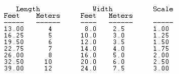
c. Dimensions. The recommended minimum overall dimensions for the marker
are 13 feet (4 m) long by 8 feet (2.5 m) wide. The width of a black border,
if used, is 1/26 the length of the marker and is included within the overall
dimensions. The following table reflects dimensions for proportionally
larger markers.
|
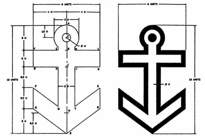
d. Layout Procedure.
1. Establish center line AB, 13 units long.
2. Establish points C, D, I, N along AB.
3. Erect perpendiculars to AB: DF, DL, IG, IK.
4. Connect points FG and KL.
5. Establish lines NP, NS, BQ, BR.
6. Connect points PQ and RS.
7. Establish points E, M, H, J, O, T.
8. Connect points HO and JT.
9. Scribe 1.5 unit radius circle about point C.
10. Extend perpendiculars from points E and M to intersect with 1.5
unit circle.
11. Scribe .5 unit radius circle about point C.
54. AVIATION FUEL.
a. Introduction. Where aviation fuel is provided at a seaplane facility, precautions must be taken to minimize the possibility of spills and the resulting adverse environmental effects of fuel spillage. Tank construction and piping should conform to the American Petroleum Institute (APR), American Society of Mechanical Engineers (ASTM), and American National Standards Institute (ANSI) standards as applicable.
b. Precautions. The following precautions should be taken to minimize the entry of water into underground tanks through improperly closed or leaking openings.
(1) All tank openings subject to frequent opening and closing should terminate above ground, using recommended pipe extensions or spools.
(2) Flush type tank openings in paved areas should be kept watertight. Inspection and maintenance manholes that are subject to frequent opening should have flanged spool covers.
(3) Below ground tanks located close to a sensitive body of water should be contained within a double wall or inside a ventilated concrete vault.
c. Dike. Above ground tanks should be surrounded by a dike designed to retain the full tank capacity of a single tank, or the capacity of the largest, plus 10 percent of the total capacity of the remaining tanks where more than one tank is installed. The dike should be constructed of impervious nonorganic soil with a plastic, liquid tight membrane. A drainage system, provided within the dike, should be designed to remove surface water and to discharge it into a drainage system capable of disposing of the fuel and water in a safe manner. Drains should normally be closed.
d. Fuel Dispensing. A fuel dispensing system usually consists of a pump, motor, strainer, meter, hose reel, hose, nozzle, automatic and manual control switches, and three-point, static discharge, electrical grounding equipment, all located above ground. The grounding and bonding system should provide electrical continuity between all metallic or conductive components; should have both ground and bonding wires, and clamps adequate to facilitate prompt, definite electrical ground connection between hose nozzle/pit/cabinet, and aircraft being fueled. A pit or cabinet should be permanently, electrically grounded. The hose reel, from an environmental and safety point of view, is an important element of this system. Ideally, an electrically operated rewind wheel should be provided to discourage the practice of "stringing out" the hose along the dock. A 5 gallon (19 l) drip pan located below the rewind reel will collect residual fuel discharge from the nozzle. State and local codes provide additional installation requirements. AC 150/5230-4, Aircraft Fuel Storage, Handling, and Dispensing On Airports, and applicable National Fire Protection Association (NFPA) standards also provide useful information.
Figure 8-1. Marker proportions.
 |
| ?AvStop Online Magazine Contact Us Return Home |