1. GENERAL NAVIGATION CONCEPTS, FAA POLICIES, AND GUIDANCE.
a. General Concepts. In the early days of aviation, few aircraft operated within any given area at the same time. The most demanding navigational requirements were to avoid obstacles and arrive at the intended destination with enough fuel remaining to safely complete a landing. As aviation evolved, the volume of air traffic grew and a corresponding need to prevent collisions increased. Today, the most significant and demanding navigational requirement in aviation is the need to safely separate aircraft. There are several factors that must be understood concerning the separation of aircraft by air traffic control (ATC).
b. Separation of Air Traffic. In many situations, ATC does not have an independent means such as radar to separate air traffic, and must depend entirely on information relayed from an aircraft to determine its actual geographic position and altitude. A flightcrew's precision in navigating the aircraft is critical to ATC's ability to provide safe separation. Even when ATC has an independent means such as radar to verify the aircraft's position, precise navigation and position reports, when required, are still the primary means of providing safe separation. In most situations, ATC does not have the capability or the responsibility for navigating the aircraft. ATC relies on precise navigation by the flightcrew. Therefore, flight safety in all instrument flight rules (IFR) operations depends directly on the operator's ability to achieve and maintain certain levels of navigational performance. ATC radar is used to monitor navigational performance, detect navigational errors, and expedite traffic flow. Any aircraft operating in accordance with ATC instructions must navigate to the level of accuracy required to comply with ATC instructions. Aircraft must be navigated with sufficient precision to avoid airspace where prior ATC clearance or ATC instructions must be obtained. For example, an aircraft flying adjacent to minimum navigation performance specifications (MNPS) airspace must fly with a degree of precision that ensures that aircraft will not inadvertently enter MNPS airspace.
c. VFR Flight. The control of air traffic requires that a certain level of navigational performance be achieved by visual flight rules (VFR) flights to ensure safe separation of aircraft and to expedite the flow of air traffic. During cruising flight, the appropriate VFR flight altitude must be maintained to ensure the required vertical separation between VFR and IFR aircraft and to assist in collision prevention. VFR aircraft must be navigated with sufficient precision to avoid weather conditions that would prevent visual contact with (and avoidance of) other aircraft, and with sufficient precision to locate a suitable airport and land safely. VFR aircraft that require navigational assistance from ATC adversely affect ATC's ability to control air traffic and expedite its flow.
d. The Concept of an ATC Clearance. Issuance of an ATC clearance by a controller, and the acceptance of this clearance by a pilot, is a negotiation process that establishes conditions for the prevention of collision hazards (inflight and terrain). When a controller issues an IFR clearance, a three-dimensional block of airspace is reserved for that aircraft along the defined route. The controller also agrees to issue clearances to all other controlled air traffic to ensure that all assigned flight routes will be safely separated. When a pilot accepts an ATC IFR clearance, that pilot is agreeing to continuously remain within the assigned three-dimensional block of airspace and to adhere to the flight rules for that operation. The pilot is obligated to comply with this agreement unless an emergency is declared or an amended clearance is received. Any deviation outside the assigned airspace creates a flight safety hazard. In such cases, the aircraft has failed to navigate to the degree of accuracy required for air traffic control and has failed to comply with Federal Aviation Regulations (FAR) and International Civil Aviation Organization (ICAO) requirements. In a nonradar environment, ATC has no independent knowledge of the aircraft's actual position or its relationship to other aircraft. Therefore, ATC's ability to detect a navigational error and resolve collision hazards is seriously degraded when a deviation from an agreed upon clearance occurs.
e. Concept of Navigation Performance. The concept of navigation performance involves the precision that must be maintained for both the assigned route and altitude by an aircraft operating within a particular area. Navigation performance is measured by the deviation (for any cause) from the exact centerline of the route and altitude specified in the ATC clearance. This includes errors due to degraded accuracy and reliability of the airborne and ground-based navigational equipment and the flightcrew's competence in using the equipment. Flightcrew competence involves both flight technical errors and navigational errors. Flight technical error is defined as the accuracy with which the pilot controls the aircraft as measured by success in causing the indicated aircraft position to match the desired position. Standards of navigational performance vary depending on traffic density and the complexity of the routes flown. Variation in traffic density is reflected in the different separation minimums applied by ATC in these two areas. For example, the minimum lateral distance permitted between co-altitude aircraft in Chicago Center's airspace is 8 nautical miles (NM) (3 NM when radar is used), while in North Atlantic (NAT) MNPS airspace it is 60 NM. The airspace assigned by ATC has lateral dimensions on both sides of the exact centerline of the route of flight specified in the ATC clearance equal to one-half of the lateral separation standard (minimum). For example, the overall level of lateral navigation performance necessary for flight safety must be within 4 NM of the airway centerline in Chicago Center's airspace, and within 30 NM in NAT MNPS airspace. FARs 121.103 and 121.121 require that each aircraft must be navigated to the degree of accuracy required for air traffic control. FAR 91.123 requirements related to compliance with ATC clearances and instructions also reflect this fundamental concept. The concept of navigational performance is also inherent in the ICAO Standards and Recommended Practices (SARP). For example, Annex 2 states that the aircraft "shall adhere to its current flight plan" and "when on an established air traffic service (ATS) route, operate along the defined centerline of that route."
f. Degree of Accuracy Required. The fundamental concept for all IFR navigation standards, practices, and procedures is that all IFR aircraft must be navigated to the degree of accuracy required for control of air traffic. When a flight remains within the assigned three-dimensional block of airspace at all times, that aircraft is considered to be navigated to the degree of accuracy required for the control of air traffic. If an aircraft deviates outside its assigned block of airspace (except during a declared emergency), that aircraft has not been navigated to the required degree of accuracy. ATC separation minimums represent the minimum dimensions of a three-dimensional block of airspace that can be assigned by ATC to control flight. These separation minimums have been established for IFR operations in controlled airspace. These standards are usually established through international agreement and implemented through national regulations. These minimums are established for particular categories of navigational operation and specified areas. Examples include navigation on airways in the national airspace of ICAO member states and long range navigation in oceanic or remote land areas. Separation minimums establish the minimum lateral, vertical, and longitudinal distances that can be used to safely separate aircraft operating within a specified area. Separation minimums also represent the minimum level of overall navigation performance which can be accommodated at any time without jeopardizing flight safety. Any aircraft deviating greater than one-half the separation minimums established for that operation has failed to meet the required level of navigational performance and to navigate to the degree of accuracy required for control of air traffic. For example, the vertical separation minimum for airplanes operating above flight level (FL) 290 in the United States is 2000 feet. Each aircraft's actual altitude must remain within + 1000 feet of the assigned altitude even when factors such as atmospheric pressure variations and instrument or pilot errors are considered. Where ATSs are provided by the United States, separation minimums are established by the FAR and ATC directives. Where ATSs are provided by contracting ICAO member states, separation minimums are established by those states' national regulations and in ICAO documents. Operations in uncontrolled airspace are not provided ATS, and separation minimums are not normally established for uncontrolled airspace. U.S. national airspace separation minimums can be found in FAA Order 7110.65, "Air Traffic Control." FAA Order 7110.83, "Oceanic Air Traffic Control," prescribes separation minimums in international oceanic airspace delegated to the United States by ICAO. ICAO Document 7030/3, "Regional Supplementary Procedures," prescribes separation minimums in international airspace.
g. FAR Part 91 Communication Equipment Requirements. FAR 91.511 states the equipment requirements, for overwater flights operating more than 30 minutes flying time or 100 NM from the nearest shore. The PIC is required to maintain a continuous listening watch on the appropriate frequency when operating under IFR in controlled airspace.
h. FAR Part 121 Communication Equipment Requirements. Communication equipment requirements for Part 121 operations are contained in FARs 121.347 and 121.349. Under FAR 121.351(a), extended overwater operations may not be conducted unless the communication requirements of FARs 121.347 and 121.349 are met. FAR 121.99 communications facilities requirements may be waived for Part 121 operators for flights over certain oceanic areas with one high frequency (HF) radio inoperative if certain conditions and limitations are met.
i. FAR Part 135 Communication Equipment Requirements. The communication equipment required for turbojet airplanes with 10 or more passenger seats and multiengine commuter airplanes are contained in FAR 135.165(a). All other aircraft operated under FAR Part 135 must meet the requirements of FAR 135.165(b). Under FAR 135.165(b)(7), aircraft are required to have an additional communication transmitter for extended overwater operations.
j. Communication Equipment Requirements for Ferry Flights. FAR 91.511 contains the requirements for radio equipment for overwater operations for ferrying FAR Parts 121 or 135 aircraft under Part 91. Certain operable communications equipment must be carried on large and turbine powered multiengine aircraft flown overwater. If both HF and very high frequency (VHF) equipment are required under FAR 91.511, FAR 91.511(d) permits overwater operations with only one HF transmitter and one HF receiver provided that the aircraft is equipped with two independent VHF transmitters and receivers.
k. Concept of Operational Service Volume. The concept of operational service volume is critical to understanding and applying the principles of air navigation. Operational service volume is the volume of airspace surrounding an ICAO standard airways navigation facility that is available for operational use. Within that volume of airspace a signal of usable strength exists and that signal is not operationally limited by cochannel interference. Within this volume of airspace, a navigational aid (navaid) facility's signal in space conforms to flight inspection signal strength and course quality standards including frequency protection. ICAO standard navaids are VHF omnidirectional radio range (VOR), VOR/distance measuring equipment (DME), and nondirectional radio beacon (NDB). The national airspace systems of ICAO contracting member states are based on the operational service volume of these facilities. Navigational performance within the operational service volume and ATC separation minimums can be predicated on the use of these facilities. In contrast, the signal-in-space outside the operational service volume has not been shown to meet the flight inspection signal strength, course quality, and frequency protection standards. Therefore, navigational performance and ATC separation minimums cannot be predicated on the use of these facilities alone.
l. Categories of Navigational Operations. A thorough comprehension of the categories of navigational operations is essential to understanding air navigation concepts and requirements, and in evaluating an operator's ability to navigate to the required degree of accuracy. In the broad concept of air navigation, two major categories of navigational operations are identified in the ensuing paragraphs:
m. Class I Navigation. Class I navigation is defined as any enroute flight operation conducted in controlled or uncontrolled airspace that is entirely within operational service volumes of ICAO standard navaids (VOR, VOR/DME, NDB). The operational service volume describes a three-dimensional volume of airspace within which any type of enroute navigation is categorized as Class I navigation. Within this volume of airspace, IFR navigational performance must be at least as precise as IFR navigation is required to be using VOR, VOR/DME (or NDB in some countries). The definition of Class I navigation is not dependent upon the equipment installed in the aircraft. For example, an aircraft equipped and approved to use Loran C in the United States as the sole means of enroute navigation (no VOR, VOR/DME installed) is conducting Class I navigation when the flight is operating entirely within the operational service volume of federal VORs and VOR/DMEs. In this example, the Loran Cs IFR navigational performance must be as precise as IFR navigation is required to be using ICAO standard navaids, if IFR operations are to be conducted. In another example, a VFR flight navigated by pilotage is conducting Class I navigation when operating entirely within the operational service volume. However, the VFR navigational performance in this example must be only as precise as VFR pilotage operations are required to be.
The lateral and vertical extent of the airspace where Class I navigation is conducted is determined solely by the operational service volumes of ICAO standard navaids. Class I navigation cannot be conducted outside of this airspace. Class I navigation also includes VFR or IFR navigation operations on the following:
* federal airways
* published IFR direct routes in the United States
* published IFR off-airway routes in the United States
* airways, advisory routes (ADR), direct routes, and off-airway routes
published or approved by a foreign government provided that these routings
are continuously within the operational service volume (or foreign equivalent)
of ICAO standard navaids
Class I navigation requirements are directly related to separation minimums used by ATC. IFR separation minimums applied in the U.S. national airspace system and most other countries are based on the use of ICAO standard navaids. These separation minimums, however, can only be applied by ATC within areas where the navaid's signal in space meets flight inspection signal strength and course quality standards. An ICAO standard navaid's signal in space conforms to flight inspection signal strength and course quality standards (including frequency protection) within its designated operational service volume. Therefore, air navigation and the safe separation of aircraft within that service volume can be predicated on the use of these facilities.
Within areas where the safe separation of aircraft is based on the use of ICAO standard navaids, any IFR operation must be navigated with at least the same precision as that specified by the appropriate national separation minimums. Any operation or portion of an operation (VFR or IFR) in controlled or uncontrolled airspace, with any navigation system (VOR, VOR/DME, NDB, Loran C, inertial navigation system (INS), Omega) or any navigational technique (dead reckoning (DR), pilotage), is Class I navigation for that portion of the route that is entirely within the operational service volume of ICAO standard enroute navaids.
n. Class II Navigation. Class II navigation is any enroute operation that is not categorized as Class I navigation and includes any operation or portion of an operation that takes place outside the operational service volumes of ICAO standard navaids. For example, an aircraft equipped with only VOR conducts Class II navigation when the flight operates in an area outside the operational service volumes of federal VORs/DMEs.
Class II navigation involves operations conducted in areas where the signals in space from ICAO standard navaids have not been shown to meet flight inspection signal strength, course quality, and frequency protection standards. Therefore, ATC cannot predicate aircraft separation on the use of these facilities alone and must apply larger separation criteria. When operating outside the operational service volume of ICAO standard navaids, signals from these stations cannot be relied upon as the sole means of conducting long range operations to the degree of accuracy required for the control of air traffic or as the sole means of obstacle avoidance. Therefore, when operating outside the designated operational service volumes of ICAO standard navaids, operators must use long range navigation systems (LRNS) (GPS, Loran C, Omega, INS) or special navigational techniques (DR, pilotage, flight navigator, celestial) or both. These systems and/or techniques are necessary to navigate to the degree of accuracy required for the control of air traffic and to avoid obstacles.
The definition of Class II navigation is not dependent upon the equipment installed in the aircraft. All airspace outside the operational service volume of ICAO standard navaids is a three-dimensional volume of airspace within which any type of enroute navigation is categorized as Class II navigation. For any type of navigation within this volume of airspace, the IFR navigational performance must be at least as precise as the navigational performance assumed during establishment of the ATC separation minimums for that volume of airspace. The navigational performance for VFR operations in a Class II navigation volume of airspace must be only as precise as VFR navigation operations are required to be.
In many cases when ATC lateral separation minimums are large (usually 90 NM or greater), and the Class II navigation portion of the flight is short (less than 1 hour), it is possible to meet required levels of navigational performance and conduct Class II navigation using ICAO standard navaids supplemented with special navigational techniques such as DR. For example, it is possible in turbojet airplanes (with proper procedures and training) to fly many routes between the southeastern United States, Caribbean Islands, and South America with VOR/DME and NDB equipment. In these situations, Class II navigation requirements can be met even though significant portions of these routes (less than 1 hour) are outside (beyond) the operational service volumes of ICAO standard navaids. In the domestic United States, it is not uncommon for low altitude VFR flights in aircraft such as helicopters to conduct Class II navigation while outside the operational service volumes of ICAO standard navaids when operating over routes of less than 100 NM in length. Obviously, Class II navigation includes transoceanic operations and operations in desolate/remote land areas such as the Arctic.
Class II navigation does not automatically require the use of long range navigation systems. In many instances, Class II navigation can be conducted with conventional navaids if special navigational techniques are used to supplement these navaids. Any portion of an enroute operation in controlled or uncontrolled airspace, with any navigation system or any navigation technique, is defined as Class II navigation for that portion of the route that is outside (beyond) the operational service volumes of ICAO standard enroute navaids.
2. LONG RANGE NAVIGATION PROCEDURES AND COLLISION AVOIDANCE.
a. Background. Recently an aircraft deviated approximately 60 miles from an assigned NAT track and came within a few feet of colliding with an aircraft assigned to an adjacent track. Following the near miss, the aircraft that had deviated from its track did not follow established contingency procedures for aircraft experiencing navigational uncertainty, thus creating the potential for further conflict with other aircraft as it returned to its assigned track. In this incident, as in the majority of incidents involving gross navigation errors (GNE), the navigation equipment DID NOT malfunction. The incident was caused by the crew's failure to operate the navigation equipment in a disciplined systematic manner during all phases of flight. The incident was further complicated by the crew's failure to comprehend the relationship between navigation performance, contingency procedure, and collision avoidance.
Although navigation errors are infrequent, human errors account for a majority of the errors attributed to aircraft equipped with automated systems. Most inadvertent navigation errors have occurred when the equipment was functioning normally, but the operating procedures prescribed were either inadequate or were not followed. Experience indicates that the increased accuracy and reliability of modem automatic navigation systems can induce a degree of complacency on the part of flightcrews, and may result in failure to routinely cross-check system performance. Under these circumstances, human errors may remain undetected for excessive periods. A common error associated with automated systems is incorrect programming of the oceanic waypoint latitudes by multiples of one degree (60 NM). In an organized track system (OTS), this can result in the flight maintaining a wrong track with high precision and thereby constituting a serious threat to other aircraft properly occupying that track and FL. Vigilance and diligence in properly applying established procedures are essential to safe oceanic navigation. Although operational procedures (checklists) may differ among navigation systems, many good practices and procedures are basic to all automated and semiautomated systems.
IFR long range operations using pilot operated electronic long range
navigation equipment shall use the practices and procedures recommended
in this advisory circular (AC). Prior to issuing operations specifications
authorizing operations requiring long range navigation equipment, the FAA
principal operations inspector (POI) should ensure that these practices
and procedures are included and emphasized in the operator's training program,
manuals, and check airman program. These basic practices and procedures
should be used in conjunction with the more detailed flight planning guidelines
in Chapter 2 of this AC. For operations currently authorized by operations
specifications or a Letter of Authorization (LOA), the operator's navigation
program should be reviewed to ensure that it follows the guidance contained
in Chapter 3 of this AC. Any deviation from these requirements must be
approved by an FAA navigation specialist through the Flight Standards National
Field Office, AFS-500 at Dulles International Airport, Washington, DC 20041.
b. Weather. In addition to the normal review of weather information concerning terminals, crews should be alert for hazardous weather that may require a flight plan change or inflight rerouting. It is important to obtain a copy of the wind flow chart (constant pressure chart or the equivalent) for the FL and route to be flown. This information may be valuable when evaluating wind forecasting errors, or if DR operations become necessary due to equipment failure. It is desirable to plot the flight route on the chart to increase its usefulness. Also, as the flight progresses, consideration should be given to plotting actual wind information on the chart as a means of evaluating the accuracy of the forecast.
c. Notices to Airmen (NOTAM). Besides checking NOTAMs for departure, destination and alternate airports, NOTAMs concerning navaids or special airspace restrictions along the planned route should be checked. Omega users should obtain NOTAMs concerning Omega station operational status to ensure that the required stations are in service. Further information concerning Omega is contained in Section 7 of this Chapter.
d. Waypoint Symbology. The navigation program should include a standard system for indicating waypoint status, as detailed below. The specific symbology recommended is noted in parenthesis. Variations in specific symbology may be necessary to accommodate the individual operator's program.
(1) Waypoint coordinates have been stored in the computer. (Enter the waypoint number next to the relevant waypoint coordinates.)
(2) Coordinates and zone distances have been independently cross- checked by a second crewmember. (Circle the waypoint number.)
(3) Coordinates and zone distances have been cross-checked during the approaching waypoint check. (Draw a diagonal line through the waypoint number.)
(4) Waypoint passage has occurred. (Draw a second diagonal line through the waypoint number.)
(5) Cross-checking during all phases of flight (flight planning, preflight, enroute).
(6) Official (master) document.
(7) Plotting.
e. Plotting Procedures. Use of plotting procedures has had a significant impact on the reduction of GNEs. The use of this technique to plot the flight route on a plotting chart and to plot the computer position approximately 10 minutes after waypoint passage are strongly recommended on all flights when long range navigation equipment is the sole means of navigation. Use of plotting procedures may be required for routes of shorter duration that transit airspace where special conditions exist, such as reduced lateral separation standards, high density traffic, or proximity to potentially hostile border areas. Plotting procedures should be required for all turbojet operations where the route segment between the operational service volume of ICAO standard navaids (VOR, VOR/DME, NDB) exceeds 725 NM, and for all turboprop operations where the route segment between the operational service volume of ICAO standard navaids exceeds 450 NM. The operational service volume is that volume of airspace surrounding a navaid which is available for operational use, within which a signal of usable strength exists, and where that signal is not operationally limited by cochannel interference. (See Section 1 of this Chapter for additional information on operational service volume.) The operational service volume for a specific navaid can be determined by contacting the Frequency Management Section within each regional Airway Facilities Division. Operational service volume includes the following:
(1) the officially designated standard service volume excluding any portion of the standard service volume that has been restricted
(2) the extended service volume
(3) within the United States (including offshore control areas (CTA)) by published instrument flight procedures (Victor or jet airways, standard instrument departures (SID), standard terminal arrivals (STAR), standard instrument approach procedures (SIAP), or instrument departure)
(4) outside the United States, any designated signal coverage or published instrument flight procedure equivalent to U.S. standards
f. Flight Planning. Many operators use a computerized navigation flight plan. Care should be taken to verify that all enroute waypoints are correctly and legibly shown on the flight plan. It is good practice to select a waypoint loading sequence and number each waypoint accordingly. If more than one copy of the flight plan is to be used, one copy should be designated as the official copy. To eliminate possible confusion, ensure that all necessary information (that is, routing changes, estimated time of arrival (ETA), waypoint loading sequence) is recorded on this flight plan, and this official copy is used for all reports to ATC. Additionally, if the flight is within the NAT OTS, obtain a copy of the current track message (ATC expects the flightcrew to have a copy) and be alert for conflict between the flight plan and the track message. Track messages are issued approximately every 12 hours and describe the NAT routes, gateways and FLs available for eastbound and westbound flights during the period indicated. While planning an overwater flight, pilots should review NOTAMs for any condition that may affect the operation and accuracy of long range navigation systems (LRNS). This is especially critical for Omega and Loran C systems, as discussed in those sections of this Chapter. The use of heading information for cross-checking must be approached with caution. In steering a given route segment with a navigation computer, the true heading required to maintain a Great Circle course will change. For example, the true heading to maintain the Great Circle course from 50 N 30 W to 50 N 40 W will be 274 degrees at 30 W, 270 degrees at 35 W, and 265 degrees at 40 W. Differences in variation along the route will further change the magnetic heading required to maintain course. The flightcrew must have a thorough understanding of the flight plan heading information and DR technique in order to use this check with any degree of certainty.
g. Navigation Preflight (at aircraft). Navigation system software identification and modification status codes should be verified. Cross-check inputs to navigation computers. Each insertion should be carried out in its entirely by one crewmember and then recalled and verified by another. Cross- check computer flight plan zone distances with zone distance displayed in navigational computers. The cross-check of coordinates and zone distances must be performed on all computer systems individually when the remote loading feature is utilized. For INS, after the systems are placed in the navigation mode, the groundspeed should be checked while the aircraft is stationary. A reading of more than a few knots may indicate an unreliable system. INS procedures are covered in Section 6 of this Chapter.
(1) Cross-check computer flight plan (CFP) gate and waypoint coordinates and identifiers with source documents (airfield diagrams, enroute charts, and NAT track messages, if applicable).
(2) Plot the flight route on a chart of appropriate scale. Operational experience has demonstrated that a scale of 1 inch to 120 NM provides the most benefit for plotting purposes.
(3) Compare routing information on ATC flight plans, computer flight
plans, NAT track messages, plotting charts, and aircraft observations and
reports (AIREP) forms.
(4) It is advisable not to copy waypoint coordinates from source documents (track message, enroute charts, etc.) to the flight plan for subsequent insertion into the navigation computers. To avoid errors in transcription, waypoint coordinates should be inserted into the computers directly from the source documents.
(5) Since the initial stage of the flight can be very busy, consideration should be given to ensuring the navigation system waypoint transfer switches are placed in the "auto" position to facilitate outbound tracking and waypoint changeover during this period.
(6) With systems such as INS or Omega that navigate during ground operations, it is advisable to cross-check present position, taxi distance, or groundspeed (as appropriate), prior to takeoff to confirm proper system operation and to ensure that the present position remains accurate.
h. Equipment Preflight. In addition to operating procedures (checklists) to confirm proper system operation, care should be taken to ensure that the navigation equipment is properly programmed. This is a very important procedure and should not be rushed. All navigation information (coordinates or courses and distances) should be programmed by one crewmember and verified by another crewmember. Also, crews should verify that the same waypoint loading sequence is used for each system and indicate on the flight plan that the present position (if applicable) and waypoints have been entered and cross-checked. If time becomes a factor, it is more important to verify that the first two or three waypoints are correct than to rush through the procedure to insert as much information as possible. Consideration should be given to using another cross-check that compares the flight plan or charted distance between waypoints and the distance computed by the navigation system to detect programming or flight planning errors. This serves as a double check on waypoint verification and will also reveal any error in the flight plan. A difference of more than + 2 NM or - 2 NM may indicate a programming or flight planning error.
i. Pretakeoff and Coast Out. Before takeoff, cross-check the computer present position to confirm proper system operation. At least two crewmembers should copy and confirm the oceanic clearance. Perform gross error check (accuracy check) to compare navigation computer position with VOR, VOR/DME, or NDB. Procedures are required for direct overflight of a navaid and for cases when the navaid is NOT directly overflown. The gross error should be recorded in the flight log. For Omega, guidance must be established for lane ambiguity resolution (refer to Section 7 of this Chapter). Outbound from gateway, cross-check VOR, VOR/DME or NDB course and distance information with navigational computers. Compass deviation check (INS only): use for DR and for determining which system is correct when there is disagreement between systems.
j. Within Range of the Outbound Gateway. Flights should not continue beyond the outbound gateway unless the required long range navigation equipment is functioning properly. To confirm proper operation, certain cross-checks should be performed while within range of the gateway navaid. Since this may be the last positive position cross-check until the inbound gateway, the following practices may also provide valuable information for resolving any later navigation difficulties.
(1) All ATC oceanic clearances should be cross-checked by two crewmembers to ensure the clearance is copied correctly. Any flight plan waypoints that were revised in an ATC clearance should be crossed out and the revised coordinates entered in a legible manner. Prior to proceeding outbound from the gateway, the current ATC clearance should be compared to the flight plan, and the information in the navigation computers for the gateway and the subsequent waypoints should be verified.
(2) A gross error check is a position accuracy cross-check using normal airway facilities such as VOR, VOR/DME or NDB. The gross error check is usually accomplished by flying directly over the gateway (if possible) and subsequently establishing the aircraft on the outbound course using the gateway navaid. This check serves the following purposes:
(a) detects errors that may have accrued in position information since
takeoff
(b) provides information that can be used to determine the most accurate
system for use as a steering reference
(c) provides an opportunity to correct position information, if necessary
(d) can be used to confirm that the aircraft is established on the
outbound course and is tracking toward the next waypoint
(e) can be used to confirm that the aircraft is proceeding according
to the current ATC clearance
(3) When flight instruments are used for the display of either airways (VOR) information or information from the LRNS, the "radio/nav" switches should be left in "radio" position after passing over the gateway navaid until the radio information begins to become degraded. The switches should then be placed in the "nav" position.
(4) Consideration should be given to performing a compass deviation check on systems such as INS that use true heading information from sources independent of the aircraft compass system. The compass deviation can be determined by comparing the INS derived data later in the flight to determine the most accurate system should a divergence between systems occur. The compass deviations can be applied to the respective compasses to determine the actual magnetic heading. Local variation can be applied to the true heading of each INS to obtain the derived magnetic headings. The most accurate INS should be the one with a magnetic heading that compares the most favorably with the actual magnetic heading.
k. After Passing the Gateway. The system determined to be the most accurate during the gross error (TKE), check should usually be selected as the autopilot steering reference. When not being used for other purposes, this system should display present position. Routinely check crosstrack, track angle error and distance to go. Display computer position coordinates and compare with ATC clearance to confirm that track centerline is maintained.
l. Approaching Waypoint. Within 2 minutes of each waypoint, both pilots should verify that the subsequent waypoint in the navigation display agrees with the current ATC clearance. Cross-check coordinates of the approaching waypoint and subsequent waypoints. Compare zone distance on the flight plan to that displayed on the navigation computer for the next leg. Compare computer flight plan ETA with ETA information displayed in navigation computers. (On some systems this cross- check may be more easily accomplished during waypoint passage.)
m. After Passing Each Waypoint. Approximately 10 minutes after passing each waypoint, the present position information on the navigation displays should be plotted on a navigation chart to confirm that the ATC clearance is satisfied (not applicable to most Doppler systems). Confirm that the navigation systems have switched to the next flight segment (leg change). Verify that the aircraft is tracking along the next flight segment (tracking outbound).
n. Approaching the Inbound Gateway. Certain preparations should be made for the transition from long range navigation to airways navigation. The following practices are recommended:
(1) As soon as feasible, set up the navigation radios to receive the inbound gateway navaid.
(2) When the gateway navaid is providing reliable information, place the "radio/nav" switch in the "radio" position and steer the aircraft to acquire and maintain the proper inbound radial/bearing.
(3) Unless otherwise directed by ATC, the aircraft should be flown directly over the gateway.
(4) When over the gateway, record the position information from the navigation displays. This information can be used to confirm system accuracy. Compare VOR, VOR/DME, NDB course and distance information with that displayed in navigation computers. It is recommended that system accuracy computations be made after arrival to avoid conflicts with other cockpit duties during the critical periods of descent, approach and landing.
o. After Arrival. The individual navigation system errors and error rates, if applicable, should be computed and recorded for future reference. It is desirable to record this information in a document that remains aboard the aircraft to provide subsequent flightcrews with a recent history of system performance. This information may be used with most systems to predict individual system performance for future flights under similar circumstances. Additionally, this information may prove valuable to subsequent flightcrews for resolving navigation abnormalities, such as divergence between systems.
3. LONG RANGE NAVIGATION PROBLEMS AND RECOMMENDED ACTIONS.
a. Background. Although the accuracy and reliability of the newer navigation systems are excellent, malfunctions and failures occasionally occur. When a malfunction occurs, flightcrews should guard against jumping to conclusions since hasty actions are seldom necessary and may further complicate the situation. Experience has shown that successful resolution of navigation difficulties in oceanic areas usually requires a thorough, thoughtful process that normally begins during preflight planning. The training program manuals and check airman program for air carrier operations should emphasize procedures to be followed in the event of partial and total instrument failure. Non air carrier operators should be prepared to demonstrate this emphasis in their training programs if requesting an LOA for oceanic operations in special airspace. The following guidance is presented for consideration when navigation difficulties are encountered or suspected.
b. Navigation Errors. Monitoring procedures used during oceanic operations indicate the frequency and course of navigation errors. Considering the thousands of flights that are made, errors are actually rather infrequent. Navigation systems are generally so reliable that there is some concern about overconfidence; therefore, crews should guard against complacency.
(1) Frequent causes of errors include the following:
(a) A mistake of one degree of latitude was made in inserting a forward waypoint.
(b) The crew was recleared by ATC, but forgot to reprogram the navigational system.
(c) The autopilot was left in the heading or decoupled position after avoiding severe weather, or was left in the VOR position after departing the last domestic airspace VOR. In some cases, this occurred after distractions by selective calling (selcal) or flight deck warning indications.
(d) The controller and crew had different understandings of the clearance because the pilot heard what he/she wanted to hear rather than what was actually said.
(2) Rare causes of errors include the following:
(a) The lat/long coordinates displayed at the gate position were incorrect.
(b) Because of a defective chip in an aircraft system, although the correct forward latitude was inserted by the crew, it "jumped" one degree.
(c) The aircraft was equipped with an advanced system that included all waypoint coordinates already on tape. The crew assumed the coordinates were correct, but one was not correct.
(d) Although the crew had the correct coordinates available, the information inserted into the system was from an incorrect company flight plan.
c. Detection of System Failure. In general, system failure is usually considered to have occurred when one of the following situations develops:
(1) a warning indicator is activated and cannot be reset;
(2) self-diagnostic or built-in test equipment (BITE) indicates that the system is unreliable;
(3) the position error over a known geographic location exceeds the maximum permissible tolerance established for a particular navigation system; or
(4) the system's operation is so abnormal that, despite the absence of warning or malfunction indications, the flightcrew considers the system no longer useful for navigation.
d. Detection of System Degradation or Malfunction. While system failures are usually straight forward malfunctions or gradual system degradations are usually more difficult to detect. This is particularly true when only two systems are on board. Navigation difficulties of this type are usually detected by a divergence between the navigation systems, a situation that often occurs gradually. This factor may reduce the possibility of identifying the faulty system unless periodic cross-checking practices are diligently used. The following factors should be considered when attempting to identify a faulty system.
(1) Check the BITE codes for indications of system fault.
(2) For Omega, the system receiving the most stations and the best quality signals should generally be the most accurate.
(3) Review the gateway gross error check for indications of the most accurate system.
(4) If a regular record of system performance has been maintained and is available, a review of the record may give a clue as to which system is faulty.
(5) If possible, use VOR, automatic direction finder (ADF), DR, airborne radar, or other navaids to obtain a position fix.
(6) Cross-check heading, groundspeed, track, and wind information between systems and compare this information with the best known positive information such as position over a fix.
(7) Attempt to contact nearby aircraft to obtain wind or groundspeed and drift correction information that may identify the malfunctioning system.
(8) The compass deviation check discussed in Section 2 of this Chapter may provide a clue as to which system is faulty for systems such as INS.
Even though these steps are taken, a divergence between systems may occur, but the flightcrew may be unable to determine which system is at fault. When this occurs, the practices described in the following paragraph should be used.
e. Recommended Actions Following System Failure. After a system malfunction or failure has been detected, ATC should be informed that the flight is experiencing navigation difficulties so that separation criteria can be adjusted, if necessary. Reporting malfunctions to ATC is an ICAO requirement and compliance is required by FAR Part 91. If the failed system can be identified with a high degree of confidence and the other system appears normal, the best course of action may be to fly the normal system and carefully monitor its performance using any additional navaids available, including DR. In the unlikely event that a total navigation failure occurs and other aids are unavailable, the only action may be to fly by DR using the flight plan headings and times. Under these circumstances, flightcrews should continue to use all means available to obtain as much navigational information as possible. Flightcrews should be alert for visual sightings of other aircraft, since a hazard may exist due to an inadvertent deviation from the assigned track. In some cases, it may be possible to establish and maintain visual contact with another aircraft on the same track.
f. Recommended Action Following a Divergence Between Systems. Since a small divergence between systems may be normal, the significance of the divergence should be evaluated. In general terms, if the divergence is less than 10 NM, the best course may be to closely monitor system performance and continue to steer the system considered most accurate. If the divergence between systems is greater than 10 NM, one of the systems may be degraded. Therefore, attempts should be made to determine which system may be faulty. If the faulty system cannot be determined using the practices described in this section, and both systems appear normal, the action most likely to limit gross tracking error may be to position the aircraft so that the actual track is midway between the crosstrack differences for as long as the position uncertainty exists. ATC should be advised that navigation difficulties are being experienced so that separation criteria may be adjusted as necessary. Consideration should be given to abandoning this "split-the-difference" practice if the divergence exceeds the separation criteria currently in effect on the route of flight. If a divergence of this magnitude occurs and the faulty system cannot be isolated, the best course may be to fly by DR using the best known wind information. However, in some cases, the best known information may be flight plan headings and times.
4. PROVING TESTS AND VALIDATION FLIGHTS.
a. Introduction. FAR Parts 121 and 135 require evaluation of an operator's ability to conduct operations safely and in accordance with the applicable regulations before issuing an operating certificate or authorizing a certificate holder to serve an area or route. The testing method used by the FAA to determine an operator's capabilities are proving tests and validation flights. FAR 121.163 and 135.145 require operators seeking authority to operate certain types of aircraft to conduct proving tests before being granted operating authority. Proving tests consist of a demonstration of ability to conduct flights and to maintain the aircraft to the appropriate standards. Proving tests should not be confused with aircraft certification tests, which are tests conducted by the aircraft manufacturer to demonstrate the airworthiness of the aircraft. FAR 121.163 requires an operator to successfully conduct proving tests before the FAA authorizes the operation of each aircraft type. FAR 135.145 requires proving tests before the FAA authorizes the operation of each type of turbojet aircraft or each type of aircraft for which two pilots are required for VFR operations. FAR 121.93, 121.113, and 135.13(a)(2) require an operator to demonstrate the ability to conduct operations over proposed routes or areas in compliance with regulatory requirements before being granted FAA authority to conduct these operations. The FAA requires validation flights for authorization to add any areas of operation beyond the continent of North America and Mexico, and. before issuance of operations specifications that authorize special means of navigation. Though proving tests and validation flights satisfy different requirements, it is common practice for operators to conduct both tests simultaneously. However, validation flights are important to consideration of oceanic operations.
b. Validation Flights. FAR 121.93, 121.113, and 135.13(a)(2) require operators to show the capability to conduct line operations safely and in compliance with regulatory requirements before being authorized to conduct those operations in revenue service. The most common method of validating an operator's capability is to observe flight operations. The FAA normally requires validation flights before issuing operations specifications granting authority to conduct operations beyond the populated areas of the North American continent. When the FAA conducts a validation flight, an in-depth review is conducted of the applicable portions of the operator's proposed procedures (especially flight following), training programs, manuals, facilities, and maintenance programs. There are four situations that require validation flights in association with approval of Class II navigation: initial approval; addition of an LRNS or a flight navigator; operations into new areas; and addition of special or unique navigation procedures. Validation flights are required when an operator proposes to conduct operations that require confirmation of the ability to operate an aircraft type within specified performance limitations. These limitations are based on the character of the terrain (or extended overwater areas), the type of operation, and the performance of the aircraft. Validation flights are also required when an operator proposes to conduct inflight or ground maneuvers that require special operational authorizations.
c. Carriage of Revenue Passengers on Validation Flights. The FAR do
not forbid the carriage of revenue passengers on validation flights. The
operator may receive FAA authorization to carry revenue passengers during
the validation flight when the proposed operation is similar to those in
the applicant's previous experience. However, carriage of revenue passengers
is normally not permitted during validation flights in the following situations:
(1) when the operator is seeking initial approval to conduct Class II navigation in any airspace designated as a special area of operation;
(2) when the operator is seeking approval to conduct Class II navigation by an LRNS or by using a flight navigator not previously approved for that means of navigation;
(3) when the operator is seeking approval to conduct Class II navigation by means of a long range navigation procedure that has not previously been approved for that operator; and
(4) when the operator has not previously operated a specific aircraft type in operations requiring special performance authorization.
d. Special Areas of Operation. Certain areas of Class II airspace are considered special operating airspace for purposes of validation. These areas include the following:
(1) extensive areas of magnetic unreliability;
(2) NAT MNPS airspace and Canadian MNPS airspace;
(3) Central Pacific (CEPAC) composite airspace and Northern Pacific
(NOPAC) airspace;
(4) Arctic Ocean and Antarctic airspace; and
(5) politically sensitive areas of operation.
e. Special Navigation Procedures. Validation flights are normally required when an applicant proposes to use navigation procedures not previously demonstrated. These procedures include the following:
(1) pilotage, including DR;
(2) flight navigator procedures;
(3) celestial navigation;
(4) pressure pattern and Bellamy drift DR;
(5) free gyro or grid procedures; and
(6) any combination of the preceding procedures.
f. Other Situations Requiring Validation Flights. Validation flights may also be required for special operational authorizations and special performance authorizations. Operators who require additional information on validation flights are encouraged to contact their local FAA flight standards district office (FSDO).
5. DOPPLER NAVIGATION - SPECIAL PROCEDURES.
In addition to the general navigational practices and procedures contained in this Chapter, the following information applies to Doppler navigation systems. A Doppler system (sensor plus computer) is a semiautomatic DR device that is less accurate than an INS or Omega system. A means of updating the Doppler is usually required if acceptable position accuracy is to be achieved on long range flights. INS, Omega or Loran C may be used as the updating reference for the Doppler system. The following factors should be considered when using a Doppler navigation system.
a. Compass Accuracy. Most Doppler systems measure groundspeed to an accuracy of about one percent and drift angle to a fraction of a degree. Its directional reference, however, is the aircraft's compass system. If the overall Doppler/compass system is to be usefully accurate, the compass should be swung and compensated so that its error does not exceed one degree on any heading.
b. Preflight. During preflight, the flight plan course and distances for those flight segments where Doppler navigation is required should be verified. Normally, the courses should be determined to the nearest one tenth of a degree and the distances to the nearest NM. This is routinely accomplished by using course and distance tables designed for this purpose. Extreme care and accuracy are important considerations during this cross-check. If the Doppler system is to be used for navigation from takeoff, both "A" and "B" stages should be programmed and the "auto/manual" switch should be placed in "auto." Also, the proper position for the "land/sea" switch should be determined since this affects the accuracy of the groundspeed information.
c. When Approaching the Outbound Gateway. The Doppler system performance records for recent flights over similar routes should be reviewed to determine if a system deviation correction should be applied. If the records indicate that a deviation correction may be necessary, apply the correction to the Doppler system used. Both pilots should verify that the outbound course and distance programmed in the active stage conforms to the currently effective ATC clearance. Unless otherwise required by ATC, the aircraft should be flown directly over the gateway fix to obtain the most accurate starting position practical. When directly over the gateway, both pilots should ensure that the Doppler computers have been activated and that the proper stage is selected. The aircraft should be established on the outbound track by using the gateway navaid. Once this is accomplished, the gross error cross-checks discussed in Section 2 above should be accomplished. Consideration should be given to using an additional cross-check. This is accomplished by applying drift angle to the compass heading and comparing the result (actual track) to the flight planned magnetic course.
d. Updating the Doppler Computer. Since Doppler systems (in a magnetically slaved model) fly a "rhumb line" (curved track) and most navigation charts commonly used reflect "Great Circle" (straight tracks), certain precautions should be observed when updating Doppler systems. Although a great circle course and a rhumb line course begin and end at common points, the two courses diverge between the waypoints. This divergence normally reaches a maximum near the midpoint of the leg, and the magnitude of the divergence increases as the latitude and distance between waypoints increase. Under normal circumstances, position fixes for Doppler updating purposes should be obtained within 75 NM of a waypoint to minimize the possibility of inducing an error into the Doppler system due to the rhumb line effect. This practice should be applied to both manually obtained and automatically obtained position fixes. When Doppler systems are used in the grid (free gyro) mode, the Doppler track will approximate a great circle, and the rhumb line effect is not a factor. Under these conditions, the updating restrictions detailed above are not normally applicable.
6. INS NAVIGATION - SPECIAL PRACTICES AND PROCEDURES.
a. Preflight. Since INS is a DR device and not a position fixing device, any error induced during alignment will be retained and possibly incremented throughout the flight unless it is removed through updating procedures. Therefore, during preflight, care should be exercised to ensure that accurate present position information is inserted into the INS. Although most INS will automatically detect large errors in present position latitude during alignment, large errors in present position longitude may exist without activating a warning indication. When cross-checking present position coordinates, be alert for the correct hemispheric indicator (that is, N, S, E, W) as well as the correct numerical values. Since most INS cannot be realigned in flight, special procedures such as ground realignment may be required to correct a significant error in present position. If the INS in use has the capability of "gang-loading" (simultaneous loading) by use of a remote feature, care should be taken so that any data entered by this method is cross-checked separately on each individual INS to detect data insertion errors. The INS software identification and modification status codes should be verified to ensure that the proper equipment is installed and the appropriate operating checklist is used. The operating checklists should include a means of ensuring that the INS is ready to navigate and that the navigation mode is activated prior to moving the aircraft. Any movement of the aircraft prior to activating the navigation mode may induce very large errors that can only be corrected by ground realignment. After the system is placed in the navigation mode, the INS groundspeed should be checked when the aircraft is stationary. An erroneous reading of more than a few knots may indicate a faulty or less reliable unit. If this occurs, a check should be made of the malfunction codes.
b. Inflight Updating. INS are essentially accurate and reliable, but it is possible to introduce errors in an attempt to improve accuracy by inflight updating. On the other hand, INS errors generally increase with time and are not self-correcting. If large tracking errors are permitted to occur, aircraft safety and separation criteria may be significantly degraded. These factors should be considered in any decision relative to inflight updating. As a guide to flightcrews, some operators consider that unless the ground facility provides a precise check and unless the error is fairly significant (for example, more than 6 NM or 2 NM/hour), it is preferable to retain the error rather than update.
7. OMEGA INFORMATION.
This section addresses only dual Omega installations. However, operators should be aware that if an operation requires two LRNS and one of the systems used is an Omega system, all requirements specified for Omega as the sole means of navigation must be met. Installations which propose to use one Omega system in combination with one or more other types of sensors or units should be evaluated on an individual basis, considering the performance of the individual systems as discussed in other sections of this Chapter.
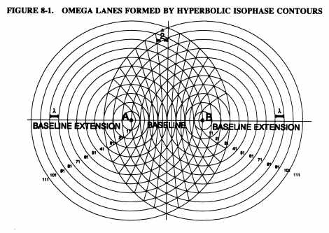
a. Background. Omega is a radio navigation system that uses a worldwide network of VLF signals from eight ground-based transmitters. The principal attributes of the Omega system are the high degree of signal stability and low signal attenuation that produce reliable position information over great distances. Various methods of signal processing are used by different manufacturers to develop position information and navigation guidance (rho-rho, hyperbolic, single frequency, 3.4 KC tracker, etc.). Because of these variations in processing methods, each design will be evaluated and approved individually. When Omega systems meet the provisions described below, they may be used as the sole means of long range navigation for operations in oceanic and/or remote land areas where adequate accuracy and reliability have been demonstrated. U.S. Navy VLF communication stations may be used to supplement Omega navigation systems. However, the U.S. Navy VLF stations are not dedicated to navigation and their signals may not be available at all times. Therefore, systems approved in accordance with this AC should be capable of operating on Omega systems alone.
The approval process is divided into two parts. The first part deals with approval under FAR Part 25 and the second part deals with operational approval under FAR Part 121. Guidance concerning compliance with FAR Part 91 regarding NAT MNPS airspace is contained in Chapter 3, Section 1 of this AC.
b. Airworthiness Approval. Applicants desiring airworthiness approval of dual Omega navigation systems in accordance with this AC should contact the appropriate FAA Regional Engineering and Manufacturing Office at least 30 days prior to start of the evaluation for processing a supplemental type certificate (STC) or type certificate (TC) amendment. A dual Omega installation includes two receiver processor units, two control display units (CDU), and two antennas.
c. Operational Approval. FAR Part 121 requirements for enroute navigation facilities are contained in FAR 121.103 and 121.121. Air carrier applicants desiring operational approval for use of dual Omega systems should contact the FSDO charged with the administration of their operating certificate a minimum of 30 days prior to the proposed start of evaluation flights. FAR Part 91 operators desiring approval of dual Omega systems for flights in MNPS airspace should contact the FSDO nearest their principal base of operations to obtain an LOA. Requests should include evidence of FAA airworthiness approval of the system, a description of the system installation, and the operator's experience with the system. Prior to presenting the initial request, an operator should have accumulated sufficient experience with the equipment to establish a history of the accuracy and reliability of the proposed system. The applicant may include previous or related operational experience of other operators who have used the same equipment on the same type aircraft, and operational experience gained during type certification or supplemental type certificate of the aircraft. Once a particular system has received an equipment approval, subsequent evaluation and approval in the same type of aircraft installations may be adjusted to avoid duplication of part of the accuracy and reliability data gathering process involved in the issuance of the original approval. A comprehensive summary of any flight experience that establishes a history of adequate signal coverage (during day or night operations), accuracy, lane ambiguity detection/resolution, and in-service reliability should be provided to show competency in the proposed operation and maintenance of the equipment.
The applicant must present proposed revisions to the operation manual, describing all normal and abnormal system operating procedures and flightcrew error protection procedures including cross-checking of data insertion, detailed methods for continuing the navigation function with partial or complete Omega system failure, reacquiring the proper lane after any power outages, and procedures for continuing operation in the event of a divergence between systems. The applicant must also present proposed revisions to the minimum equipment fist (MEL) concerning Omega, with appropriate justification. The applicant must present a list of operations to be conducted using the system including an analysis of each operation with respect to signal reception for ground synchronization and enroute operation, signal absorption by the Greenland Icecap, sufficient redundancy of signal coverage to permit continued operation during station outages, procedures for operating in areas of magnetic compass unreliability (if applicable), availability of other enroute navaids, and adequacy of gateway facilities to support the system. (For the purpose of this AC, a gateway is a specific navigation fix where the use of LRNS commences or terminates.) The operator must develop a procedure for timely dissemination of Omega NOTAM information to crewmembers. The operator must also develop an outline of the maintenance program for the equipment, including training of maintenance personnel, positioning of spares and test equipment, maintenance manual revision procedures (if applicable), and the other means of compliance with the requirements of FAR Part 121, Subpart L.
The Omega navigation system should be checked inflight to determine that the design and installation criteria are met. All modes of operation should be functionally checked. The airplane flight manual procedures should be evaluated inflight, including abnormal and emergency procedures. This evaluation should include reinitialization, lane ambiguity resolution, etc., during normal and adverse conditions. Interfaced equipment should be evaluated to ensure proper operation. Normal flight maneuvering should include 180 degree turns to verify dynamic response. An applicant for airworthiness approval should provide data from sufficient flights in the area of intended use to show that the Omega navigation system can meet the accuracy requirements stipulated for LRNS in FAR 37.205 {sic.}, technical standard order (TSO) C-94, and Radio Technical Commission for Aeronautics (RTCA) DO-164, Section III, paragraph 3.8. Consideration should be given to time of day, season, station outages, station geometry, and poor signal to noise ratio.
(1) It should be demonstrated that operation of the system does not impose an unacceptable workload in a normal flight environment on the flightcrew. This aspect should receive careful scrutiny relative to crew workload during power outages, DR operations, and detecting/resolving lane ambiguities.
(2) The DR mode should be evaluated to determine the maximum period for which interim use is permissible. The information should be included in the airplane flight manual.
d. Ground Evaluation. After installation, an operational/functional check should be performed to demonstrate compatibility between the Omega system and aircraft electrical and electronic systems. This test should be conducted with all electrical/electronic equipment operating normally on aircraft power. A ground location should be selected that minimizes the presence of external electromagnetic interference. In addition, it should be demonstrated that the Omega equipment will not adversely affect other systems to which it may be connected; that is, air data, autopilot, flight director, and compass system. The Omega velocity and heading (or track) information presented on the control display unit (CDU) and other interfacing instruments should have reasonable comparison to the primary indications on other flight deck instruments. During these tests, the primary velocity and heading inputs to the Omega system should be slewed through their operating range to ensure compatibility of input to interfaced equipment. This evaluation may be conducted inflight. Displays of all data basic to the installed Omega systems should be demonstrated to show no instability or discontinuity utilizing those stations identified by the system as usable and necessary for navigation. This evaluation may be conducted inflight.
e. Evaluation and Final Approval. Prior to final approval for the use of Omega as a sole means of long range navigation, a thorough evaluation of an operator's training program and a flight evaluation by an FAA inspector will be required. This flight evaluation should be requested on the operator's application for the use of Omega as a sole means of long range navigation.
(1) The evaluation by an FAA inspector will include the adequacy of operating procedures and training programs; availability of terminal, gateway, area, and enroute ground based navaids; operational accuracy; equipment reliability; and acceptable maintenance procedures. Omega equipment operations should be closely analyzed to ensure that an unacceptable workload is not imposed upon the flightcrew by use of the Omega equipment in normal and abnormal operations.
(2) After the evaluation is completed, FAA approval is indicated by issuance of operations specifications for air carriers and by an LOA for other operators who desire to fly in airspace where an authorization is required. The operations specifications (or amendments thereto) authorizing the use of dual Omega as a sole means of long range navigation in the areas in which operations were demonstrated by an air carrier will limit the operations to areas where compliance with FAR Part 121 or FAR Part 135 requirements were demonstrated. Requirements for LOAs are detailed in Chapter 3 of this AC.
(3) The operations specifications should contain applicable limitations or special requirements needed for particular routes or areas and, where necessary, list a sufficient number of Omega ground transmitters required to be in operation to provide the necessary amount of signal redundancy.
f. Minimum Functions Necessary When Used for Position Fixing and Sole Means of Navigation. Dual independent Omega navigation systems used as a position-fixing device or position- keeping device and sole means of navigation should meet the performance requirements of TSO C-94, "Airborne Omega Receiving Equipment" and Section 3 of RTCA Document No. DO-164 titled "Minimum Performance Standards Airborne Omega Receiving Equipment" dated March 19, 1976. When installed, the system should provide a means of entry for at least the following data inputs and functions:
(1) present position (initializing, reinitialization and update);
(2) waypoints;
(3) heading, wind and true airspeed (TAS); or track and groundspeed; or other external information required for operation in the secondary or direct ranging mode;
(4) time;
(5) date;
(6) deselection and reselection of any station (automatic deselection and reselection is acceptable if shown to be effective and reliable); and
(7) lane ambiguity resolution. Automatic lane ambiguity resolution is acceptable if shown to effective and reliable.
g. System Displays. If the equipment is to be operated by the pilot(s), the system controls and data display should be visible to, and usable by, each pilot seated at a pilot duty station. The system controls should be arranged to provide adequate protection against inadvertent system turnoff. The system should also provide a means of displaying the following information:
(1) present position
(2) time
(3) date
(4) synchronization status
(5) station(s) deselected - station(s) selected
(6) time and position recall in event of power failure for up to 7 minutes
(7) annunciation when system is not operating in the primary Omega navigation mode
(8) a visual or aural warning of system failure, malfunctions, power interruption, lack of synchronization, or operation without adequate signals
(9) waypoint coordinates
(10) bearing and distance between waypoints
(11) deviation from desired course
(12) distance and time to go to selected waypoint
(13) track angle and/or error
(14) drift angle
(15) wind, TAS and heading; or track and groundspeed
(16) stations currently being installed to determine position
(17) steering information on the horizontal situation indicator (HSI) or equivalent
(18) confirmation of data insertion
h. Failure Protection. Normal operation or probable failure of the airborne Omega navigation system should not derogate the normal operation of interfaced equipment. Likewise, the failure of interfaced equipment should not render an Omega system inoperative.
i. Environmental Conditions. The Omega equipment should be capable of performing its intended function over the environmental ranges expected to be encountered in actual operations. RTCA Document No. DO-160 should be used for appropriate guidelines.
j. Antenna Performance. The antenna design and installation should minimize the effects of precipitation (p) static and other noise of disturbances.
k. Dynamic Responses. The system operation should not be adversely affected by aircraft maneuvering or changes in attitude encountered in normal operations.
l. Preflight Test. A preflight test capability should be provided to inform the flightcrew of system status.
m. Aircraft Electrical Power Source. One Omega system should be installed so that it receives electrical power from a bus that provides maximum reliability without jeopardizing essential or emergency loads assigned to that bus. The other Omega system should be installed so that it receives power from a different bus that provides a high degree of reliability. Any electrical power transient, including inflight selection of another source of power, should not adversely effect the operation of either Omega system. After power interruption of 7 + or - 2 seconds, the Omega equipment should automatically resynchronize and resume normal operation within 3 minutes without operator intervention. After a power interruption of greater than 7 seconds and up to 7 minutes, the Omega equipment should either automatically resume normal operation (including proper lane resolution) or retain the last "power-on" Omega equipment position and time for display on command. A battery, if shown to be of sufficient capacity, may be used to provide power for this function. The Omega navigation system should not be the source of objectionable electromagnetic interference, nor be adversely affected by electromagnetic interference from other equipment in the aircraft.
n. Steering Outputs. The Omega system should provide steering outputs to the autopilot and/or HSI or equivalent so that the equipment interface is compatible.
o. Airplane Flight Manual. The airplane flight manual should contain the following information regarding the Omega equipment:
(1) normal procedures for operating the equipment
(2) equipment operating limitations
(3) emergency/abnormal operating procedures (if applicable)
(4) procedures for reacquiring the proper lane after power outages
p. Demonstration of Performance. An applicant for approval of dual Omega navigation system installation should ensure that the installed Omega system can demonstrate adequate performance by a combination of ground and flight evaluations defined in the following two paragraphs.
q. Equipment and Equipment Installation. Omega navigation systems should be installed in accordance with the airworthiness approved system installation requirements. If evaluation flights are made for operations requiring an LRNS, a navigation system already approved for the operator under FAR Part 121 should be used as the primary means of navigation.
r. Omega Training Programs. The training program curriculum must include initial and recurrent training and checking for those crewmembers who will be operating the Omega equipment. Initial training programs should include the following:
(1) Instruction regarding responsibilities of flight crewmembers, dispatchers and maintenance personnel.
(2) For the flightcrews who are to operate the Omega equipment, instruction in the following:
(a) description of the Omega network, airborne system description, limitations, and detection of malfunctions;
(b) normal operating procedures including preflight procedures and testing, data insertion and cross-checking, enroute procedures including periodic cross-checking of system position display and comparison between systems;
(c) updating procedures, if applicable;
(d) operations in areas of magnetic compass unreliability, if applicable;
(e) abnormal and emergency procedures, including airborne conditions, procedures for assessing and resolving divergence between systems, and procedures for reacquiring the proper lane in case of power outages in excess of 7 seconds;
(f) a review of navigation, including flight planning and applicable meteorology as necessary, if not addressed in another approved training course; and
(g) compilation of terminal and/or gateway system errors.
(3) Procedures for operating the Omega navigation system should be incorporated into the recurrent training program for those crewmembers who are to operate the Omega equipment.
(4) For flight crewmembers without previous Omega experience, the training and qualification program should include an inflight qualification check based on the training program. Accomplishment of such training during evaluation flights is acceptable. Sufficient flightcrews considered fully qualified by the applicant should be observed inflight by an FAA inspector to determine the overall effectiveness of the training and qualification program. Flightcrews possessing current operational experience with the installed Omega equipment need only receive training specifying any differences in procedures created by using Omega as a sole means of long range navigation, if applicable.
(5) Annual line checks as required by FAR 121.440 should include a check of Omega operating procedures. Required annual checks of flight navigators, if they are to operate the Omega equipment, should also include a check of these procedures.
s. Accuracy and Reliability. The applicant should show the following:
(1) That an adequate inflight service reliability rate stated in terms of inflight mean time between failures (MTBF) is in existence, with no significant unresolved problems remaining.
(2) That in the process of proposed operation, the Omega navigation system meets the accuracy requirements stipulated for Omega navigation systems. If the proposed system is to be operated in areas with special navigation requirements (for example, MNPS airspace), the accuracy required for those areas must also be demonstrated. Systems that become exceedingly inaccurate without displaying a warning indication should be included in the accuracy accounting. Systems that display a failure warning and are subsequently shut down or disregarded should be included in the accounting of failed systems but excluded from the accuracy accounting.
(3) That Omega navigation systems which are subject to lane ambiguity have a reliable means of reacquiring the proper lane.
(4) That the Omega sole means system can meet navigation separation requirements and have sufficient signal redundancy to continue navigation during Omega station outages. Equipment having the capability to process the U.S. Navy VLF signals may utilize that feature to refine Omega information to assist in meeting this stipulation.
(5) That within the proposed area of operation, navigation capability is not predicated on the DR mode, and that any interim operation in DR does not degrade navigation accuracy and reliability beyond that required to comply with ATC requirements.
t. Special Practices and Procedures. Since the CDUs of most Omega systems
are similar in appearance to those used for INS, persons familiar with
INS may have a tendency to assume that Omega has similar performance characteristics.
This assumption could create significant problems. INS is a precision DR
device which is wholly self-contained within the aircraft and has a nominal
position degradation of about 1 mile per hour of flight. Omega, in contrast,
continuously resolves aircraft position by processing radio signals received
from a global network of transmitters. It is therefore possible for Omega
to be affected by signal propagation disturbances and abnormally high local
radio noise levels. In normal operation, Omega provides a position accuracy
of 1 to 3 NM which, unlike INS, does not degrade with increasing flight
time. However, most Omega systems compute position in signal "lanes," which
are a function of the signal wavelength. A disturbance of sufficient magnitude
may force the computed position into an adjacent lane and thereby cause
an error which is measured in multiples of the basic lane width. This occurrence
is termed a "lane slip." Most Omega systems possess an auxiliary operating
mode termed "lane ambiguity resolution" (LAR). The purpose of this mode
is to correct the lane slip by returning the present position to the correct
lane. Details of lane ambiguity follow.
FIGURE 8-1. OMEGA LANES FORMED BY HYPERBOLIC ISOPHASE CONTOURS
u. Omega Lanes Formed by Hyperbolic Isophase Contours. (Figure 8-1) The set of isophase contours between a station pair forms a series of lanes, each corresponding to one complete cycle of phase difference. in the direct ranging mode, lanes are formed by concentric rings of zero phase with a constant interval of one wavelength (16 NM at 10.2 kilohertz (kHz)). In the hyperbolic mode, one complete cycle of phase difference occurs every one half wavelength. Therefore, 10.2 kHz hyperbolic lanes are 8 NM wide on the baseline, and gradually diverge as the distance from the baseline increases. Each lane, or cycle of the phase, is divided into hundredths of a lane called centilanes (cel). The phase difference between station pairs, measured in -hundredths of a cycle or centicycles (cec), gives a hyperbolic line of position (LOP) within an Omega lane. (The term cel refers to the fraction of the charted lane. The term cec refers to the phase measurement as a percentage of a cycle. At 102 kHz, they are numerically equal and often used interchangeably, with cec used most commonly.) For example, in Figure 8-2 phase differences of 20 cec and 50 cec between stations A and B would give LOPs as shown. Twenty cec would indicate an LOP 20 percent of a lane width from the lane boundary; 50 cec would indicate an LOP 50 percent of a lane width from the lane boundary. Fractional lane widths are taken from a given lane boundary toward the direction of the station with the letter designation occurring later in the alphabet (from the "lower" letter to the "higher" letter). Since the same phase difference will be observed at any point on an LOP, a second LOP must be taken using another station pair to obtain a position fix. In Figure 8-3, the phase difference A-B is 50 cec, and the phase difference B-C is 80 cec. The intersection of these LOPs gives a position fix. In actual practice, propagation corrections (PPC would be applied to the observed phase difference readings before plotting.
FIGURE 8-2. PHASE MEASUREMENT WITHIN AN OMEGA LANE
FIGURE 8-3. POSITION FIX BY INTERSECTION OF HYPERBOLIC LOPS
v. Lane Ambiguity. in the preceding examples, it is assumed that the aircraft's position is known to within a particular set of lanes. Because of the cyclic nature of the phase differences, the same phase difference can be observed in any lane. This is known as lane ambiguity. On the baseline between station pairs, there are about 600 10.2 kHz lanes. Each lane is 8 NM wide on the baseline, and diverges to about 12 - 15 NM near the limits of coverage. The navigator must know which of these lanes the aircraft is in before plotting a fix. Lane ambiguity can be resolved by three methods. The preferred method is to set the receiver's lane count at a known location, such as the point of departure. As the aircraft moves across lane boundaries, the receiver will automatically update the lane identification numbers, allowing the navigator to plot fixes with phase difference measurements in a known lane. If the lane count is lost, the lane count must be reset based on DR, celestial fix, or other means. The third alternative is to derive a course lane using multiple frequencies.
The preceding examples have considered only 10.2 kHz. Many receivers are capable of using the other Omega frequencies for various purposes. One such purpose is lane ambiguity resolution. There is a 3:4 frequency ratio between 10.2 kHz and 13.6 kHz. This relationship also applies to other wavelengths. Three 10.2 kHz wavelengths are the same length as four 13.6 wavelengths (Figure 8-4), or 24 NM on the baseline in the hyperbolic mode (48 NM in the direct ranging mode). A wavelength of 24 NM would correspond to a frequency of 3.4 kHz, which is the difference between 10.2 and 13.6 kHz. The receiver can synthesize a 3.4 kHz Omega signal by combining the 10.2 and 13.6 kHz signals. The 10.2 kHz lane numbers, which are evenly divisible by 3, form the boundaries of 3.4 kHz course lanes (Figure 8-5). The 3.4 kHz phase differences can be plotted in these course lanes. The resulting fix is then used to reset the 10.2 kHz lane count.
FIGURE 8-4. USING FREQUENCY DIFFERENCES TO DERIVE COURSE LANES
FIGURE 8-5. COURSE LANE BOUNDARIES IN THE HYPERBOLIC MODE
w. Omega Navigation System Center. The Omega Navigation System Center (ONSCEN) is the Coast Guard unit responsible for the operational control of Omega. ONSCEN is staffed on weekdays between 7:00 am. and 3:30 pm, eastern time. During these hours information on Omega, including the current system status, scheduled off-air periods, and any navigational warnings in effect may be obtained by calling (703) 866-3800. At other times a command duty officer (CDO) is on watch and can be contacted by calling the same number; a recorded message will give the name and telephone number of the CDO. Written inquiries may be addressed to: Commanding Officer, Omega Navigation System Center, 7323 Telegraph Road, Alexandria, VA 22310-3998. A recorded message giving the current status of Omega is available at any time by calling (703) 866-3801. This recording gives the dates and times of scheduled off-air periods, any navigational warnings in effect due to signal disturbances, and any other important system information. Routine Omega status reports and navigational warnings are also available through the following means.
(1) Telex/mail. Omega status reports are issued weekly by telex or mail to users of Omega equipment. Navigational warnings are not issued by telex or mail. Write to ONSCEN at the address given above.
(2) Radio broadcast. The U.S. Department of Commerce (DOC), National Institutes of Standards and Technology, broadcasts Omega status advisories on radio stations WWV, Fort Collins, CO and WWVH, Kauai, HA on 2.5, 5, 10, and 15 megahertz (MHz). WWV also broadcasts on 20 MHz. Omega status advisories are broadcast at 16 minutes past each hour on WWV, and at 47 minutes past each hour on WWVH. These advisories contain dates for scheduled off-airs and any navigational warnings in effect. Because each announcement is limited to 40 seconds, the specific times for each off-air period may not be given.
(3) NOTAM. When alerted by the Coast Guard, the FAA issues NOTAMs to warn of signal disturbances or unscheduled off-air periods. Airmen should consult their local FAA office for details regarding the issuance of Omega NOTAMs.
x. Aviation Use of Omega. Whereas INS position errors normally accrue gradually with elapsed flight time, most Omega errors occur suddenly and are usually multiples of the basic lane width. Effective cross-checking procedures should be accomplished at regular intervals and LAR or inflight updating should be initiated when the position accuracy is in doubt. In addition to the general practices and procedures contained in Section 1, above, the following recommendations apply to Omega systems.
(1) Preflight.
(a) Crews should be alert for any NOTAMs affecting the operational status of the individual Omega transmitters, particularly for possible abnormal operation. Deselection of any station reported to be in abnormal operation should be considered at the onset of the flight. Also, crews should be alert for any NOTAMs relating to the propagation disturbances, such as sudden ionospheric disturbances, sudden phase anomalies, or polar cap anomalies, which may affect Omega positioning accuracy. Scheduled Omega status broadcasts on station WWV should be monitored as a means of obtaining current Omega information.
(b) The Omega software and modification status codes should be verified by flightcrews to ensure that the proper equipment is installed and that the appropriate checklist is available and is used.
(c) At certain ground locations, particularly at congested terminals, abnormally high radio noise levels may adversely affect Omega. For example, synchronization may take longer than normal or the inserted ramp coordinates may drift after insertion. Synchronization or DR warning lights usually indicate this situation. This problem normally disappears, if the Omega equipment is serviceable, shortly after the switch to aircraft power or after the aircraft is moved from the gate. Care should be exercised during taxi, since abrupt turns may cause a momentary loss of signals which could affect system accuracy. It is good practice to cross-check present position coordinates or taxi distance before takeoff to detect any errors which may have occurred since initialization.
(2) Inflight Updating. The same considerations basic to updating an INS also apply to Omega due to the normal accuracy and reliability of these systems. However, in addition to the capability to update over a navaid, most Omega systems are capable of performing an LAR if certain signal strength and station geometry requirements are met. Unless an apparent Omega error exceeds 6 NM, a lane slip may not necessarily have occurred and LAR or updating is not normally recommended. If an LAR appears to be necessary, the LAR should be initiated on only one system at a time so that the other system remains unaffected for use as a cross-check. The LAR should be attempted first on the system believed to be the least accurate.
y. Navigation Errors by Omega Equipped Aircraft. If a navigation error is discovered by a crew of an Omega equipped aircraft, or if a crew of an Omega equipped aircraft is notified of a navigation error by ATC, a report containing the information listed in Figure 8-6 should be submitted to the FAA. This information should be sent by mail or facsimile (fax) to the FSDO nearest the aircraft's base of operation or, if applicable, to the FSDO that holds the operator's operating certificate.
FIGURE 8-6. NAVIGATION DEVIATION REPORT FOR OMEGA EQUIPPED AIRCRAFT
|
8. GLOBAL POSITIONING SYSTEMS (GPS) GENERAL INFORMATION.
a. GPS Navigation. The GPS is a satellite-based radio navigation system that uses precise range measurements from GPS satellites to determine a precise position anywhere in the world. The GPS constellation consists of 24 satellites in various orbital planes approximately 11,000 nautical miles (NM) above the earth. The satellites broadcast a timing signal and data message that the airborne equipment processes to obtain satellite position and status data, and to measure how long each satellite's radio signal takes to reach the receiver. By knowing the precise location of each satellite and precisely matching timing with the atomic clocks on the satellites, the receiver can accurately measure the time the signal takes to arrive at the receiver and thus determine the satellite's precise position. A minimum of three satellites must be in view to determine a two-dimensional position. Four satellites are required to establish an accurate three-dimensional position. GPS equipment determines its position by precise measurement of the distance from selected satellites in the system and the satellite's known location. The accuracy of GPS position data can be affected by various factors. Many of these accuracy errors can be reduced or eliminated with mathematics and sophisticated modeling, while other sources of errors cannot be corrected. The following are examples of those errors which cannot be corrected:
(1) Atmospheric propagation delays can cause relatively small measurement errors, typically less than 100 feet. Ionospheric propagation delays can be partially corrected by sophisticated error-correction capabilities.
(2) Slight inaccuracies in the atomic clocks on the satellites can cause a small position error of approximately 2 feet.
(3) Receiver processing (such as mathematical rounding and electrical interference) may cause errors that are usually either very small (which may add a few feet of uncertainty into each measurement) or very large (which are easy to detect). Receiver errors are typically on the order of 4 feet.
(4) Conditions that cause signal reflections before the satellite's transmitted signal gets to the receiver can cause small errors in position determination or momentary loss of the GPS signal. While advanced signal processing techniques and sophisticated antenna design are used to minimize this problem, some uncertainty can still be added to a GPS measurement.
(5) A satellite's exact measured orbital parameters (ephemeris data) can contain a small error of approximately 4 feet.
b. System Operation.
(1) The Department of Defense (DOD) is responsible for operating the GPS satellite constellation and constantly monitors the GPS satellites to ensure proper operation. Every satellite's ephemeris data are sent to each satellite for broadcast as part of the data message sent in the GPS signal. The GPS is a system of cartesian earth-centered, earth-fixed coordinates as specified in the DOD World Geodetic System 1984 (WGS-84). Navigation values, such as groundspeed and distance and bearing to a waypoint, are computed from the aircraft's latitude/longitude and the location of the waypoint. Course guidance is usually provided as a linear deviation from the desired track of a Great Circle course between defined waypoints.
(2) GPS navigation capability from the 24 satellite constellation is available 24 hours a day anywhere in the world. GPS status is broadcast as part of the data message transmitted by the satellites. Additionally, system status is planned to be available through Notices to Airmen (NOTAM). Status information is also available by means of a telephone data service from the U.S. Coast Guard. Availability of suitable navigation capability from the satellite constellation is expected to approach 100 percent.
(3) GPS signal integrity monitoring will be provided by the GPS navigation
receiver using receiver autonomous integrity monitoring (RAIM). For GPS
sensors that provide position data only to an integrated navigation system
(for example, FMS, multisensor navigation system), a level of GPS integrity
equivalent to that of RAIM may be provided by the integrated navigation
system. Availability of RAIM capability to meet nonprecision approach requirements
in the United States with the 24 satellite constellation is expected to
exceed 99 percent.
c. Selective Availability (SA). SA is essentially a method by which DOD can artificially create a significant clock and ephemeris error in the satellites. This feature is designed to deny an enemy nation or terrorist organization the use of precise GPS positioning data. SA is the largest source of error in the GPS system. When SA is active, the DOD guarantees horizontal position accuracy will not be degraded beyond 100 meters 95 percent of the time, and beyond 300 meters 99.99 percent of the time.
d. Portable Units. All portable electronic systems and portable GPS units must be handled in accordance with the provisions of FAR 91.21. The operator of the aircraft must determine that each portable electronic device will not cause interference with the navigation and communications systems of the aircraft on which it is to be used. Portable GPS units which are attached by Velcro tape or hard yoke mount that require an antenna (internally or externally mounted) are considered to be portable electronic devices and are subject to the provisions of FAR 91.21. All portable GPS equipment attached to the aircraft by a mounting device must be installed in an approved manner and in accordance with FAR Part 43. Questions concerning installation should be referred to an avionics or airworthiness inspector. A critical aspect of any GPS installation is the installation of the antenna. Shadowing by the aircraft structure can adversely affect the operation of the GPS equipment. FAA approval of avionic components, including antennas, requires an evaluation of the applicable aircraft certification regulations prior to approval of an installation. The regulations require that the components perform their intended functions and be free of hazards in and of themselves and to other systems as installed. Pilots should be aware that a GPS signal is weak, typically below the value of the background noise. Electrical noise or static in the vicinity of the antenna can adversely affect the performance of the system. It is recommended that system installations be flight tested in conjunction with other navigation equipment prior to using the system for actual navigation. Unless a portable GPS receiver is TSO C-129 approved, it is not to be used as a basis for approval of operations in the NAT MNPS.
e. Navigation Classes. All navigation performed in flight is either Class I or Class II navigation.
(1) Class I navigation: Any enroute flight operation or portion of a flight operation conducted in an area entirely within the officially designated operational service volumes of ICAO standard airways navigation facilities (VOR, VOR/DME, NDB). The two generic types of Class I navigation are navigation by direct reference to ICAO standard navaids and navigation by use of area navigation systems.
(2) Class II navigation: Any operation or portion of an enroute operation which takes place outside (beyond) the officially designated operational service volumes of ICAO standard navaids (VOR, VOR/DME, NDB). Any enroute flight operation or portion of a flight operation which is not Class I navigation. There are three generic classes of Class II navigation. These are navigation by reference to ICAO standard navaids supplemented by dead reckoning, navigation by use of pilot-operated electronic long range navigation systems (for example INS, Omega, GPS), and navigation by use of a flight navigator.
f. RAIM. A technique whereby a civil GPS receiver/processor determines the integrity of the GPS navigation signals using only GPS signals or GPS signals augmented with altitude. This determination is achieved by a consistency check among a series of satellites being tracked. At least one satellite in addition to those required for navigation must be in view for the receiver to perform the RAIM function.
g. Supplemental Air Navigation System. An FAA approved navigation system that can be used in addition to a required means of air navigation. May be used as the primary navigation system provided an operational approved alternate means of navigation suitable for the route of flight is installed on the aircraft.
h. System Availability. The percentage of time (specified as 98 percent)
that at least 21 of the 24 satellites must be operational and providing
a usable navigation signal.
9. FAA APPROVAL OF GPS EQUIPMENT.
a. GPS Equipment Classes. GPS equipment is categorized into classes A(), B(), and C() (ref. TSO C-129).
(1) Class A(). Equipment incorporating both the GPS sensor and navigation capability. This equipment incorporates RAIM.
* Class A1 equipment includes enroute, terminal, and nonprecision approach
navigation capability
* Class A2 equipment includes enroute and terminal navigation capability
only.
(2) Class B(). Equipment consisting of a GPS sensor that provides data to an integrated navigation system (that is, flight management system, multi-sensor navigation system, etc.).
* Class B1 equipment includes RAIM and provides enroute, terminal, and
nonprecision approach capability.
* Class B2 equipment includes RAIM and provides enroute and terminal
capability only.
* Class B3 equipment requires the integrated navigation system to provide
a level of GPS integrity equivalent to RAIM and provides enroute, terminal,
and nonprecision approach capability.
* Class B4 equipment requires the integrated navigation system to provide
a level of GPS integrity equivalent to RAIM and provides enroute and terminal
capability only.
(3) Class C(). Equipment consisting of a GPS sensor that provides data to an integrated navigation system (that is, flight management system, multi-sensor navigation system, etc.), which provides enhanced guidance to an autopilot or flight director in order to reduce flight technical error. Installation of Class C() equipment is limited to aircraft approved under FAR Part 121 or equivalent criteria.
* Class C1 equipment includes RAIM and provides enroute, terminal, and
nonprecision approach capability.
* Class C2 equipment includes RAIM and provides enroute and terminal
capability only.
* Class C3 equipment requires the integrated navigation system to provide
a level of GPS integrity equivalent to RAIM and provides enroute, terminal,
and nonprecision approach capability.
* Class C4 equipment requires the integrated navigation system to provide
a level of GPS integrity equivalent to RAIM and provides enroute and terminal
capability only.
NOTE: Operators requiring additional GPS approval information are referred to the following ACs: AC 20-130, "Airworthiness Approval of Multi-Sensor Navigation Systems for Use in the U.S. National Airspace System (NAS) and Alaska," and AC 20-XXX {AC 20-138}, "Airworthiness Approval of Global Positioning System (GPS) Navigation Equipment for Use as a VFR and IFR Supplemental Navigation System" (This AC was formerly FAA Notice N8110.47).
b. Approval Criteria. A GPS installation with a TSO C-129 authorized
navigation system in Class A1, A2, B1, B2, C1, or C2 may be used in combination
with other approved LRNS for unrestricted operations in NAT MNPS airspace
or may be used as the sole means of long range navigation on the special
routes that have been developed for aircraft equipped with only one LRNS
and on the special routes developed for aircraft equipped with short range
navigation equipment. The basic integrity for these operations must be
provided by RAIM or an equivalent method. A single GPS installation in
Class A1, A2, B1, B2, C1, or C2 which provides RAIM for integrity monitoring
may also be used on those short oceanic routes which have only one required
means of long range navigation.
c. Avionics. Documentation must be provided which validates approval of the installed GPS airborne receiver in accordance with Notices 8110.47, 8110.48, AC 20-129 and AC 20-130A, as appropriate, or other applicable airworthiness criteria established for GPS installations. When it has been established that the airborne system has been certified for GPS IFR operations, the following criteria should be used to determine the operational suitability of airborne systems for GPS IFR use:
(1) Initial Installations and Continued Airworthiness. The operator must ensure that the equipment is properly installed and maintained. No special requirements, other than the standard practices currently applicable to navigation or landing systems, have been identified that are unique to GPS, for example, Airworthiness Directives, Service Bulletins.
(2) Action. Aviation safety inspectors must evaluate installation (An avionics inspector should evaluate the avionics installation and recommend the approval prior to the issuance of an LOA to operate in NAT MNPS airspace.), crew capabilities, and operational responsibilities relative to GPS oceanic operations prior to issuing an LOA for operation in MNPS. Specific items to check are as follows:
(a) The GPS navigation equipment used must be approved in accordance with the requirements specified in TSO C-129 and the installation must be made in accordance with Notice 8110.47 or 8110.48 or the AFS/AIR joint guidance memorandum dated July 20, 1992.
(b) The basic integrity for these operations must be provided by RAIM or an equivalent method.
(c) The GPS operation must be conducted in accordance with the FAA approved flight manual or flight manual supplement, if required.
(d) Aircraft using GPS equipment under IFR must be equipped with an approved and operational alternate means of navigation appropriate to the route to be flown. This traditional navigation equipment must be actively used by the flightcrew to monitor the performance of the GPS system.
(e) Procedures must be established for use in the event that significant GPS navigation outages are predicted to occur. In situations where this is encountered, the flight must rely on other approved equipment, delay departure, or cancel the flight.
(f) Aircraft navigating by GPS are considered to be RNAV aircraft. Therefore, the appropriate equipment suffix must be included in the ATC flight plan.
10. GPS OPERATIONS SPECIFICATIONS.
Air carrier operators planning on utilizing GPS are required to have their operations specifications amended prior to performing operations utilizing GPS. The specific operations specifications items that must be considered are as follows:
* Enroute authorization for class I navigation.
* Enroute authorization for class II navigation using a single GPS.
* Enroute authorization for class II navigation using GPS and a second
Long Range Navigation System.
* Authorization for use of GPS in Central East Pacific (CEPAC) Airspace.
* Authorization for use of GPS in Northern Pacific (NOPAC) Airspace.
* Authorization for use of GPS in North Atlantic MNPS Airspace.
* Authorization to conduct operations in Areas of Magnetic Unreliability
with GPS.
* Authorization for use of GPS to conduct Nonprecision Instrument Approach
Procedures in Airplanes.
* Authorization for use of GPS to conduct Nonprecision Instrument Approach
Procedures in Rotorcraft.
Approaches using GPS equipment are subject to the following limitations:
(1) The GPS equipment used must be approved for EPR operations, including nonprecision approaches, and the GPS constellation and the required airborne equipment must be providing the levels of accuracy, continuity and integrity required for that operation.
(2) The flightcrew must have successfully completed the approved training program and demonstrated competency in these operations.