|
SECONDARY AREA
The secondary obstacle clearance area extends along a
line 2 NM on each side of the primary area. Navigation
system accuracy in the secondary area has widths of
route protection of a ±6.7° angle from the NAVAID.
These 6.7° lines intersect the outer boundaries of the secondary
areas at the same point as primary lines, 51 NM
from the NAVAID. If the distance from the NAVAID to
the COP is more than 51 NM, the secondary area
extends along the 6.7° line when the COP is at midpoint.
In all areas, mountainous and nonmountainous,
obstacles that are located in secondary areas are considered
as obstacles to air navigation if they extend
above the secondary obstacle clearance plane. This
plane begins at a point 500 feet above the obstacles
upon which the primary obstacle clearance area is
based, and slants upward at an angle that causes it to
intersect the outer edge of the secondary area at a point
500 feet higher. [Figure 3-10]
The obstacle clearance areas for LF airways and routes
are different than VHF, with the primary and secondary
area route widths both being 4.34 NM. The accuracy
lines are 5.0° in the primary obstacle clearance area and
7.5° in the secondary area. Obstacle clearance in the
primary area of LF airways and routes is the same as
that required for VHF, although the secondary area
obstacle clearance requirements are based upon distance
from the facility and location of the obstacle
relative to the inside boundary of the secondary area.

When a VHF airway or route terminates at a NAVAID or
fix, the primary area extends beyond that termination
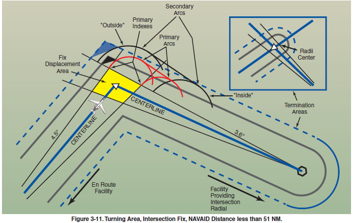
point. Figure 3-11 and its inset show the construction of
the primary and secondary areas at the termination
point. When a change of course on VHF airways and
routes is necessary, the en route obstacle clearance
turning area extends the primary and secondary
obstacle clearance areas to accommodate the turn
radius of the aircraft. Since turns at or after fix passage
may exceed airway and route boundaries, pilots
are expected to adhere to airway and route protected
airspace by leading turns early before a fix. The
turn area provides obstacle clearance for both turn
anticipation (turning prior to the fix) and flyover
protection (turning after crossing the fix). This does
not violate the requirement to fly the centerline of the
airway. Many factors enter into the construction and
application of the turning area to provide pilots with
adequate obstacle clearance protection. These may
include aircraft speed, the amount of turn versus
NAVAID distance, flight track, curve radii, MEAs,
and minimum turning altitude (MTA). A typical protected
airspace is shown in Figure 3-11. Turning area
system accuracy factors must be applied to the most
adverse displacement of the NAVAID or fix and the
airway or route boundaries at which the turn is made.
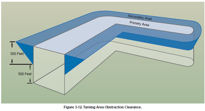
If applying nonmountainous en route turning area criteria
graphically, depicting the vertical obstruction
clearance in a typical application, the template might
appear as in Figure 3-12 .


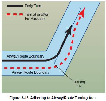
Turns that begin at or after fix passage may exceed the
protected en route turning area obstruction clearance.
Figure 3-13 on page 3-10 contains an example of a
flight track depicting a turn at or after fix passage,
together with an example of an early turn. Without
leading a turn, an aircraft operating in excess of 290
knots true airspeed (TAS) can exceed the normal airway
or route boundaries depending on the amount of
course change required, wind direction and velocity,
the character of the turn fix (DME, overhead navigation
aid, or intersection), and pilot technique in making
a course change. For example, a flight operating at
17,000 feet MSL with a TAS of 400 knots, a 25° bank,
and a course change of more than 40° would exceed the
width of the airway or route; i.e., 4 NM each side of
centerline. Due to the high airspeeds used at 18,000
feet MSL and above, additional IFR separation protection
for course changes is provided.

|


