There are two general types of ac motors used in aircraft systems: induction motors and synchronous motors. Either type may be single phase, two phase, or three phase.
Three phase induction motors are used where large amounts of power are required. They operate such devices as starters, flaps, landing gears, and hydraulic pumps.
Single phase induction motors are used to operate devices such as surface locks, intercooler shutters, and oil shutoff valves in which the power requirement is low.
Three phase synchronous motors operate at constant synchronous speeds and are commonly used to operate flux gate compasses and propeller synchronizer systems.
Single phase synchronous motors are common sources of power to operate electric clocks and other small precision equipment. They require some auxiliary method to bring them up to synchronous speeds; that is, to start them. Usually the starting winding consists of an auxiliary stator winding.
Three Phase Induction Motor
The three phase ac induction motor is also called a squirrel cage motor. Both single phase and three phase motors operate on the principle of a rotating magnetic field. A horseshoe magnet held over a compass needle is a simple illustration of the principle of the rotating field. The needle will take a position parallel to the magnetic flux passing between the two poles of the magnet. If the magnet is rotated, the compass needle will follow. A rotating magnetic field can be produced by a two or three phase current flowing through two or more groups of coils wound on inwardly projecting poles of an iron frame. The coils on each group of poles are wound alternately in opposite directions to produce opposite polarity, and each group is connected to a separate phase of voltage. The operating principle depends on a revolving, or rotating, magnetic field to produce torque. The key to understanding the induction motor is a thorough understanding of the rotating magnetic field.
Rotating Magnetic Field
The field structure shown in A of figure 9-83 has poles whose windings are energized by three ac voltages, a, b, and c. These voltages have equal magnitude but differ in phase, as shown in B of figure 9-83.
At the instant of time shown as 0 in B of figure 9-83, the resultant magnetic field produced by the application of the three voltages has its greatest intensity in a direction extending from pole 1 to pole 4. Under this condition, pole 1 can be considered as a north pole and pole 4 as a south pole.
At the instant of time shown as 1, the resultant magnetic field will have its greatest intensity in the direction extending from pole 2 to pole 5; in this case, pole 2 can be considered as a north pole and pole 5 as a south pole. Thus, between instant 0 and instant 1, the magnetic field has rotated clockwise.
At instant 2, the resultant magnetic field has its greatest intensity in the direction from pole 3 to pole 6, and the resultant magnetic field has continued to rotate clockwise.
At instant 3, poles 4 and 1 can be considered as north and south poles, respectively, and the field has rotated still farther.
At later instants of time, the resultant magnetic field rotates to other positions while traveling in a clockwise direction, a single revolution of the field occurring in one cycle. If the exciting voltages have a frequency of 60 cps, the magnetic field makes 60 revolutions per second, or 3,600 rpm. This speed is known as the synchronous speed of the rotating field.
Construction of Induction Motor
The stationary portion of an induction motor is called a stator, and the rotating member is called a rotor. Instead of salient poles in the stator, as shown in A of figure 9-83, distributed windings are used; these windings are placed in slots around the periphery of the stator.
It is usually impossible to determine the number of poles in an induction motor by visual inspection, but the information can be obtained from the nameplate of the motor. The nameplate usually gives the number of poles and the speed at which the motor is designed to run. This rated, or nonsynchronous, speed is slightly less than the synchronous speed. To determine the number of poles per phase on the motor, divide 120 times the frequency by the rated speed; written as an equation:
![]()
where: P is the number of poles per phase, f is the frequency in cps, N is the rated speed in rpm, and 120 is a constant.
The result will be very nearly equal to the number of poles per phase. For example, consider a 60 cycle, three phase motor with a rated speed of 1,750 rpm. In this case:
![]()
|
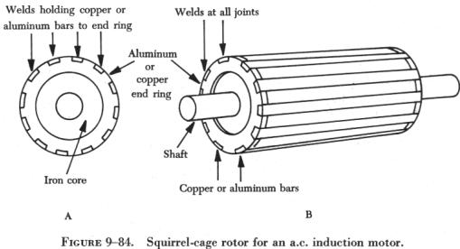
The rotor of an induction motor consists of an iron core
having longitudinal slots around its circumference in which heavy copper
or aluminum bars are embedded. These bars are welded to a heavy ring of
high conductivity on either end.
The composite structure is sometimes called a squirrel cage, and motors containing such a rotor are called squirrel cage induction motors. (See figure 9-84.) Induction Motor Slip When the rotor of an induction motor is subjected to the revolving magnetic field produced by the stator windings, |
 |
Single Phase Induction Motor
The previous discussion has applied only to polyphase motors. A single phase motor has only one stator winding. This winding generates a field which merely pulsates, instead of rotating. When the rotor is stationary, the expanding and collapsing stator field induces currents in the rotor. These currents generate a rotor field opposite in polarity to that of the stator. The opposition of the field exerts a turning force on the upper and lower parts of the rotor trying to turn it 180° from its position. Since these forces are exerted through the center of the rotor, the turning force is equal in each direction. As a result, the rotor does not turn. If the rotor is started turning, it will continue to rotate in the direction in which it is started, since the turning force in that direction is aided by the momentum of the rotor.
Shaded Pole Induction Motor
 |
In figure 9-86, a diagram of a pole and the rotor is shown. The poles
of the shaded pole motor resemble those of a dc motor.
A low resistance, short circuited coil or copper band is placed across one tip of each small pole, from which, the motor gets the name of shaded pole. The rotor of this motor is the squirrel cage type. As the current increases in the stator winding, the flux increases. A portion of this flux cuts the low resistance shading coil. This induces a current in the shading coil, and by Lenz's law, the current sets up a flux which opposes the flux inducing the current. Hence, most of the flux passes through the unshaded portion of the poles, as shown in figure 9-86. |
When the current in the winding and the main flux reaches a maximum, the rate of change is zero; thus, no e.m.f. is induced in the shading coil. A little later, the shading coil current, which causes the induced e.m.f. to lag, reaches zero, and there is no opposing flux. Therefore, the main field flux passes through the shaded portion of the field pole.
The main field flux, which is now decreasing, induces a current in the shading coil. By Lenz's law, this current sets up a flux which opposes the decrease of the main field flux in the shaded portion of the pole. The effect is to concentrate the lines of force in the shaded portion of the pole face.
In effect, the shading coil retards, in time phase, the portion of the flux passing through the shaded part of the pole. This lag in time phase of the flux in the shaded tip causes the flux to produce the effect of sweeping across the face of the pole, from left to right in the direction of the shaded tip. This behaves like a very weak rotating magnetic field, and sufficient torque is produced to start a small motor.
The starting torque of the shaded pole motor is exceedingly weak, and the power factor is low. Consequently, it is built in sizes suitable for driving such devices as small fans.
Split Phase Motor
There are various types of self starting motors, known as split phase motors. Such motors have a starting winding displaced 90 electrical degrees from the main or running winding. In some types, the starting winding has a fairly high resistance, which causes the current in this winding to be out of phase with the current in the running winding. This condition produces, in effect, a rotating field and the rotor revolves. A centrifugal switch disconnects the starting winding automatically, after the rotor has attained approximately 25 percent of its rated speed.
Capacitor Start Motor
With the development of high capacity electrolytic capacitors, a variation of the split phase motor, known as the capacitor start motor, has been made. Nearly all fractional horsepower motors in use today on refrigerators, oil burners, and other similar appliances are of this type. (See figure 9-87.) In this adaptation, the starting winding and running winding have the same size and resistance value. The phase shift between currents of the two windings is obtained by using capacitors connected in series with the starting winding.
Capacitor start motors have a starting torque comparable to their torque at rated speed and can be used in applications where the initial load is heavy. Again, a centrifugal switch is required for disconnecting the starting winding when the rotor speed is approximately 25 percent of the rated speed.
Although some single phase induction motors are rated as high as 2 hp (horsepower), the major field of application is 1 hp, or less, at a voltage rating of 115 volts for the smaller sizes and 110 to 220 volts for one-fourth hp and up. For even larger power ratings, polyphase motors generally are used, since they have excellent starting torque characteristics.
Direction of Rotation of Induction Motors
The direction of rotation of a three phase induction motor can be changed by simply reversing two of the leads to the motor. The same effect can be obtained in a two phase motor by reversing connections to one phase. In a single phase motor, reversing connections to the starting winding will reverse the direction of rotation.
Most single phase motors designed for general application have provision for readily reversing connections to the starting winding. Nothing can be done to a shaded pole motor to reverse the direction of rotation because the direction is determined by the physical location of the copper shading ring.
If, after starting, one connection to a three phase motor is broken, the motor will continue to run but will deliver only one-third the rated power. Also, a two phase motor will run at one-half its rated power if one phase is disconnected. Neither motor will start under these abnormal conditions.
Synchronous Motor
|
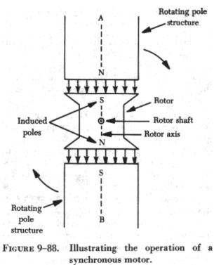
An understanding of the operation of the synchronous motor
can be obtained by considering the simple motor of figure 9-88. Assume
that poles A and B are being rotated clockwise by some mechanical means
in order to produce a rotating magnetic field, they induce poles of opposite
polarity in the soft iron rotor, and forces of attraction exist between
corresponding north and south poles.
Consequently, as poles A and B rotate, the rotor is dragged along at the same speed. However, if a load is applied to the rotor shaft, the rotor axis will momentarily fall behind that of the rotating field but, thereafter, will continue to rotate with the field at the same speed, as long as the load remains constant. If the load is too large, the rotor will pull out of synchronism with the rotating field and, as a result, will no longer rotate with the field at the same speed. The motor is then said to be overloaded. Such a simple motor as that shown in figure 9-88 is never used. The idea of using some mechanical means of rotating the poles is impractical because another motor would be required to perform this work. Also, such an arrangement is unnecessary because a rotating magnetic field can be produced electrically by using phased ac voltages. In this respect, the synchronous motor is similar to the induction motor. |
 |
The synchronous motor consists of a stator field winding similar to that of an induction motor. The stator winding produces a rotating magnetic field. The rotor may be a permanent magnet, as in small single phase synchronous motors used for clocks and other small precision equipment, or it may be an electromagnet, energized from a dc source of power and fed through slip rings into the rotor field coils, as in an alternator. In fact, an alternator may be operated either as an alternator or a synchronous motor.
Since a synchronous motor has little starting torque, some means must be provided to bring it up to synchronous speed. The most common method is to start the motor at no load, allow it to reach full speed, and then energize the magnetic field. The magnetic field of the rotor locks with the magnetic field of the stator and the motor operates at synchronous speed.
The magnitude of the induced poles in the rotor shown in figure 9-89 is so small that sufficient torque cannot be developed for most practical loads. To avoid such a limitation on motor operation, a winding is placed on the rotor and energized with dc. A rheostat placed in series with the dc source provides the operator of the machine with a means of varying the strength of the rotor poles, thus placing the motor under control for varying loads.
The synchronous motor is not a self starting motor. The rotor is heavy and, from a dead stop, it is impossible to bring the rotor into magnetic lock with the rotating magnetic field. For this reason, all synchronous motors have some kind of starting device. One type of simple starter is another motor, either ac or dc, which brings the rotor up to approximately 90 percent of its synchronous speed. The starting motor is then disconnected, and the rotor locks in step with the rotating field. Another starting method is a second winding of the squirrel cage type on the rotor. This induction winding brings the rotor almost to synchronous speed, and when the dc is connected to the rotor windings, the rotor pulls into step with the field. The latter method is the more commonly used.
AC Series Motor
An alternating current series motor is a single phase motor, but is not an induction or synchronous motor. It resembles a dc motor in that it has brushes and a commutator. The ac series motor will operate on either ac or dc circuits. It will be recalled that the direction of rotation of a dc series motor is independent of the polarity of the applied voltage, provided the field and armature connections remain unchanged. Hence, if a dc series motor is connected to an ac source, a torque will be developed which tends to rotate the armature in one direction. However, a dc series motor does not operate satisfactorily from an ac supply for the following reasons:
1. The alternating flux sets up large eddy current and hysteresis losses in the unlaminated portions of the magnetic circuit and causes excessive heating and reduced efficiency.
2. The self induction of the field and armature windings causes a low power factor.
3. The alternating field flux establishes large currents in the coils, which are short circuited by the brushes; this action causes excessive sparking at the commutator.
|
1. The eddy current losses are reduced by laminating the field poles,
frame and armature.
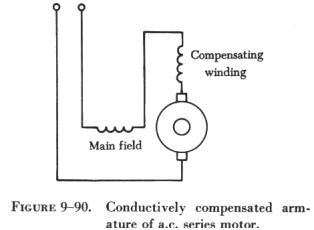
2. Hysteresis losses are minimized by using high permeability, transformer-type, silicon steel laminations. 3. The reactance of the field windings is kept satisfactorily low by using shallow pole pieces, few turns of wire, low frequency (usually 25 cycles for large motors), low flux density, and low reluctance (a short airgap). 4. The reactance of the armature is reduced by using a compensating winding embedded in the pole pieces. If the compensating winding is connected in series with the armature, as shown in figure 9-90, the armature is conductively compensated. |
 |
|
|
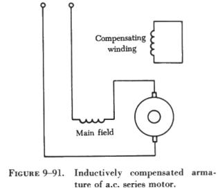
If the compensating winding is designed as shown in figure 9-91, the
armature is inductively compensated. If the motor is designed for operation
on both dc and ac circuits, the compensating winding is connected in series
with the armature. The axis of the compensating winding is displaced from the main field axis by an angle of 90°. This arrangement is similar to the compensating winding used in some dc motors and generators to overcome armature reaction. The compensating winding establishes a counter magnetomotive force, neutralizing the effect of the armature magnetomotive force, preventing distortion of the main field flux, and reducing the armature reactance. The inductively compensated armature acts like the primary of a transformer, the secondary of which is the shorted compensating winding. The shorted secondary receives an induced voltage by the action of the alternating armature flux, and the resulting current flowing through the turns of the compensating winding establishes the opposing magnetomotive force, neutralizing the armature reactance. |
|
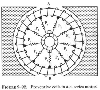
5. Sparking at the commutator is reduced by the use of preventive leads
P1, P2, P3, and so forth, as shown in figure 9-92, where a ring armature
is shown for simplicity. When coils at A and B are shorted by the brushes,
the induced current is limited by the relatively high resistance of the
leads.
Sparking at the brushes is also reduced by using armature coils having only a single turn and multipolar fields. High torque is obtained by having a large number of armature conductors and a large diameter armature. Thus, the commutator has a large number of very thin commutator bars and the armature voltage is limited to about 250 volts. Fractional horsepower ac series motors are called universal motors. They do not have compensating windings or preventive leads. They are used extensively to operate fans and portable tools, such as drills, grinders, and saws. |
 |