 |
|
| INSTRUMENT PROCEDURES HANDBOOK |
|
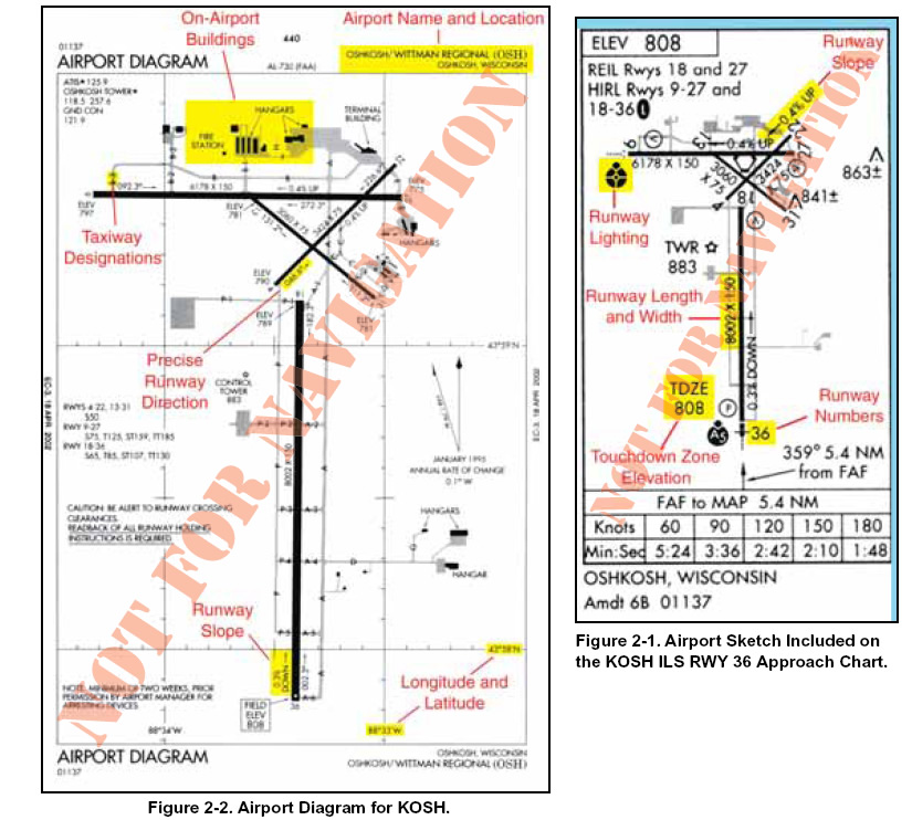
SAFETY IN THE DEPARTURE ENVIRONMENT Thousands of IFR takeoffs and departures occur daily in the National Airspace System (NAS). In order to accommodate this volume of Instrument Flight Rule (IFR) traffic, Air Traffic Control (ATC) must rely on pilots to use charted airport sketches and diagrams as well as standard instrument departures (SIDs) and obstacle departure procedures (ODPs). While many charted (and uncharted) departures are based on radar vectors, the bulk of IFR departures in the NAS require pilots to navigate out of the terminal environment to the en route phase. IFR takeoffs and departures are fast-paced phases of flight, and pilots often are overloaded with critical flight information. During takeoff, pilots are busy requesting and receiving clearances, preparing their aircraft for departure, and taxiing to the active runway. During IFR conditions, they are doing this with minimal visibility, and they may be without constant radio communication if flying out of a non-towered airport. Historically, takeoff minimums for commercial operations have been successively reduced through a combination of improved signage, runway markings and lighting aids, and concentrated pilot training and qualifications. Today at major terminals, some commercial operators with appropriate equipment, pilot qualifications, and approved Operations Specifications (OpsSpecs) may takeoff with visibility as low as runway visual range (RVR) 3, or 300 feet runway visual range. One of the consequences of takeoffs with reduced visibility is that pilots are challenged in maintaining situational awareness during taxi operations. SURFACE MOVEMENT SAFETY One of the biggest safety concerns in aviation is the surface movement accident. As a direct result, the FAA has rapidly expanded the information available to pilots including the addition of taxiway and runway information in FAA publications, particularly the IFR U.S. Terminal Procedures Publication (TPP) booklets and Airport/Facility Directory (A/FD) volumes. The FAA has also implemented new procedures and created educational and awareness programs for pilots, air traffic controllers, and ground operators. By focusing resources to attack this problem head on, the FAA hopes to reduce and eventually eliminate surface movement accidents. AIRPORT SKETCHES AND DIAGRAMS Airport sketches and airport diagrams provide pilots of all levels with graphical depictions of the airport layout. The National Aeronautical Charting Office (NACO) provides an airport sketch on the lower left or right portion of every instrument approach chart. [Figure 2-1]
This sketch depicts the runways, their length, width, and slope, the touchdown zone elevation, the lighting system installed on the end of the runway, and taxiways. For select airports, typically those with heavy traffic or complex runway layouts, NACO also prints an airport diagram. The diagram is located in the IFR TPP booklet following the instrument approach chart for a particular airport. It is a fullpage depiction of the airport that includes the same features of the airport sketch plus additional details such as taxiway identifiers, airport latitude and longitude, and building identification. The airport diagrams are also available in the A/FD and on the NACO website, http://naco.faa.gov. by selecting “Online digital - TPP.” [Figure 2-2]
|