 |
|
| INSTRUMENT PROCEDURES HANDBOOK |
|
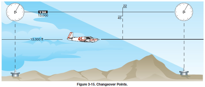
CHANGEOVER POINTS When flying airways, pilots normally change frequencies
midway between navigation aids, although there
are times when this is not practical. If the navigation
signals cannot be received from the second VOR at the
midpoint of the route, a changeover point (COP) is
depicted and shows the distance in NM to each NAVAID,
as depicted in Figure 3-15 on page 3-12. COPs indicate
the point where a frequency change is necessary to
receive course guidance from the facility ahead of the
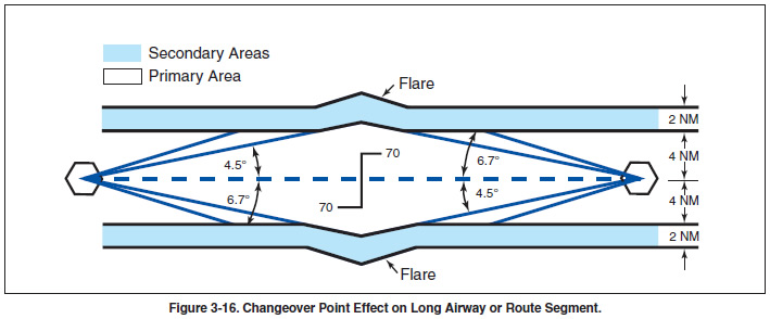
aircraft instead of the one behind. These changeover
points divide an airway or route segment and ensure
continuous reception of navigation signals at the prescribed
minimum en route IFR altitude. They also
ensure that other aircraft operating within the same portion
of an airway or route segment receive consistent
azimuth signals from the same navigation facilities
regardless of the direction of flight.
|