 |
|
| INSTRUMENT PROCEDURES HANDBOOK |
|
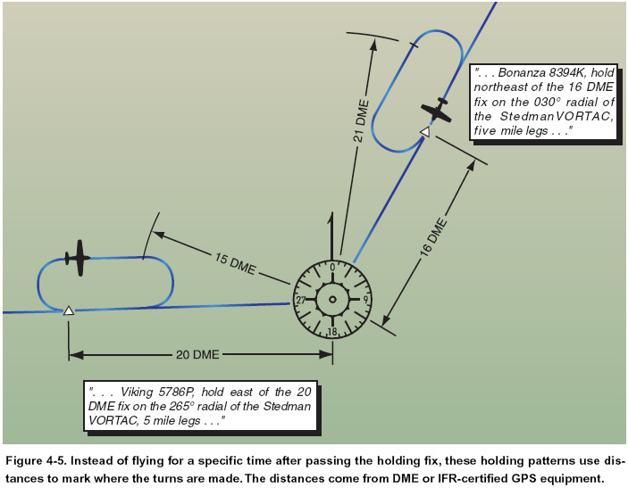
CRUISE CLEARANCE The term "cruise" may be used instead of "maintain" to assign a block of airspace to an aircraft. The block extends from the minimum IFR altitude up to and including the altitude that is specified in the cruise clearance. On a cruise clearance, you may level off at any intermediate altitude within this block of airspace. You are allowed to climb or descend within the block at your own discretion. However, once you start descent and verbally report leaving an altitude in the block to ATC, you may not return to that altitude without an additional ATC clearance. A cruise clearance also authorizes you to execute an approach at the destination airport. When operating in uncontrolled airspace on a cruise clearance, you are responsible for determining the minimum IFR altitude. In addition, your descent and landing at an airport in uncontrolled airspace are governed by the applicable visual flight rules (VFR) and/or Operations Specifications (OpsSpecs), i.e., CFR, 91.126, 91.155, 91.175, 91.179, etc. HOLDING PATTERNS If you reach a clearance limit before receiving a further clearance from ATC, a holding pattern is required at your last assigned altitude. Controllers assign holds for a variety of reasons, including deteriorating weather or high traffic volume. Holding might also be required following a missed approach. Since flying outside the area set aside for a holding pattern could lead to an encounter with terrain or other aircraft, you need to understand the size of the protected airspace that a holding pattern provides. Each holding pattern has a fix, a direction to hold from the fix, and an airway, bearing, course, radial, or route on which the aircraft is to hold. These elements, along with the direction of the turns, define the holding pattern. Since the speed of the aircraft affects the size of a holding pattern, maximum holding airspeeds have been designated to limit the amount of airspace that must be protected. The three airspeed limits are shown in Figure 3-31 in Chapter 3 of this book. Some holding patterns have additional airspeed restrictions to keep faster airplanes from flying out of the protected area. These are depicted on charts by using an icon and the limiting airspeed. Distance-measuring equipment (DME) and IFR-certified global positioning system (GPS) equipment offer some additional options for holding. Rather than being based on time, the leg lengths for DME/GPS holding patterns are based on distances in nautical miles. These patterns use the same entry and holding procedures as conventional holding patterns. The controller or the instrument approach procedure chart will specify the length of the outbound leg. The end of the outbound leg is determined by the DME or the along track distance (ATD) readout. The holding fix on conventional procedures, or controller-defined holding based on a conventional navigation aid with DME, is a specified course or radial and distances are from the DME station for both the inbound and outbound ends of the holding pattern. When flying published GPS overlay or standalone procedures with distance specified, the holding fix is a waypoint in the database and the end of the outbound leg is determined by the ATD. Instead of using the end of the outbound leg, some FMSs are programmed to cue the inbound turn so that the inbound leg length will match the charted outbound leg length. Normally, the difference is negligible, but in high winds, this can enlarge the size of the holding pattern. Be sure you understand your aircraft’s FMS holding program to ensure that the holding entry procedures and leg lengths match the holding pattern. Some situations may require pilot intervention in order to stay within protected airspace. [Figure 4-5]
|