 |
|
| INSTRUMENT PROCEDURES HANDBOOK |
|
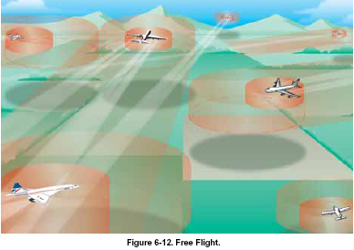
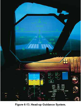
In the U.S., the national route program (NRP), also known as “Free Flight,” is an example of applying RNAV techniques. The NRP is a set of rules and procedures that are designed to increase the flexibility of user flight planning within published guidelines. The Free Flight program allows dispatchers and pilots to choose the most efficient and economical route for flights operating at or above FL 290 between city pairs, without being constrained to airways and preferred routes. Free Flight is a concept that allows you the same type of freedom you have during a VFR flight. Instead of a NAS that is rigid in design, pilots are allowed to choose their own routes, or even change routes and altitudes at will to avoid icing, turbulence, or to take advantage of winds aloft. Complicated clearances become unnecessary, although flight plans are required for traffic planning purposes and as a fallback in the event of lost communication. Free Flight is made possible with the use of advanced avionics, such as GPS navigation and datalinks between your aircraft, other aircraft, and controllers. Separation is maintained by establishing two airspace zones around each aircraft, as shown in Figure 6-12. The protected zone, which is the one closest to the aircraft, never meets the protected zone of another aircraft. The alert zone extends well beyond the protected zone, and aircraft can maneuver freely until alert zones touch. If alert zones do touch, a controller may provide the pilots with course suggestions, or onboard traffic displays may be used to resolve the conflict. The size of the zones is based on the aircraft’s speed, performance, and equipment. Free Flight is operational in Alaska, Hawaii, and part of the Pacific Ocean, using about 2,000 aircraft. Full implementation is projected to take about 20 years. As the FAA and industry work together, the technology to help Free Flight become a reality is being placed into position, especially through the use of the GPS satellite system. Equipment such as ADS-B allows pilots in their cockpits and air traffic controllers on the ground to “see” aircraft traffic with more precision than has previously been possible. The FAA has identified more than 20 ways that ADS-B can make flying safer. It can provide a more efficient use of the airspace and improve your situational awareness. Head-up displays (HUDs) grew out of the reflector gun sights used in fighter airplanes before World War II. The early devices functioned by projecting light onto a slanted piece of glass above the instrument panel, between the pilot and the windscreen. At first, the display was simply a dot showing where bullets would go, surrounded by circles or dots to help the pilot determine the range to the target. By the 1970s, the gun sight had become a complete display of flight information. By showing airspeed, altitude, heading, and aircraft attitude on the HUD glass, pilots were able to keep their eyes outside the cockpit more of the time. Collimators make the image on the glass appear to be far out in front of the aircraft, so that the pilot need not change eye focus to view the relatively nearby HUD. Today’s head-up guidance systems (HGS) use holographic displays. Everything from weapons status to approach information can be shown on current military HGS displays. This technology has
obvious value for civilian aviation, but until 1993 no civilian HGS systems were available. This is changing, and application of HGS technology in airline and corporate aircraft is becoming widespread. [Figure 6-13]
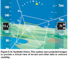
A large fraction of aircraft accidents are due to poor visibility. While conventional flight and navigation instruments generally provide pilots with accurate flight attitude and geographic position information, their use and interpretation requires skill, experience, and constant training. NASA is working with other members of the aerospace community to make flight in low visibility conditions more like flight in visual meteorological conditions (VMC). Synthetic vision is the name for systems that create a visual picture similar to what the pilot would see out the window in good weather, essentially allowing a flight crew to see through atmospheric obscurations like haze, clouds, fog, rain, snow, dust, or smoke. The principle is relatively simple. GPS position information gives an accurate three-dimensional location, onboard databases provide detailed information on terrain, obstructions, runways, and other surface features, and virtual reality software combines the information to generate a visual representation of what would be visible from that particular position in space. The dynamic image can be displayed on a head-down display (HDD) on the instrument panel, or projected onto a HGS in such a way that it exactly matches what the pilot would see in clear weather. Even items that are normally invisible, such as the boundaries of special use airspace or airport traffic patterns, could be incorporated into such a display. While the main elements of such a system already exist, work is continuing to combine them into a reliable, safe, and practical system. Some of the challenges include choosing the most effective graphics and symbology, as well as making the synthetic vision visible enough to be useful, but not so bright that it overwhelms the real view as actual terrain becomes visible. Integrating ADS-B information may make it possible for synthetic vision systems to show other aircraft. [Figure 6-14]
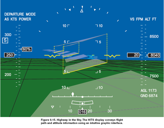
A natural extension of the synthetic vision concept is the highway in the sky (HITS) program. This technology adds an easy-to-interpret flight path depiction to an electronic flight instrument system (EFIS) type of cockpit display, which may be located on the instrument panel or projected on a HUD. The intended flight path is shown as a series of virtual rectangles that appear to stand like a series of window frames in front of the aircraft. The pilot maneuvers the aircraft so that it flies “through” each rectangle, essentially following a visible path through the sky. When installed as part of a general aviation “glass cockpit,” this simple graphic computer display replaces many of the conventional cockpit instruments, including the attitude indicator, horizontal situation indicator, turn coordinator, airspeed indicator, altimeter, vertical speed indicator, and navigation indicators. Engine and aircraft systems information may also be incorporated. [Figure 6-15]
|