 |
|
| INSTRUMENT PROCEDURES HANDBOOK |
| HELICOPTER FLIGHT MANUAL LIMITATIONS Helicopters are certificated for IFR operations with
either one or two pilots. Certain equipment is required
to be installed and functional for two-pilot operations
and additional equipment is required for single pilot
operation.
In addition, the Helicopter Flight Manual defines systems
and functions that are required to be in operation
or engaged for IFR flight in either the single or twopilot
configurations. Often, in a two-pilot operation,
this level of augmentation is less than the full capability
of the installed systems. Likewise, a single-pilot
operation may require a higher level of augmentation.
The Helicopter Flight Manual also identifies other specific
limitations associated with IFR flight. Typically,
these limitations include, but are not limited to:
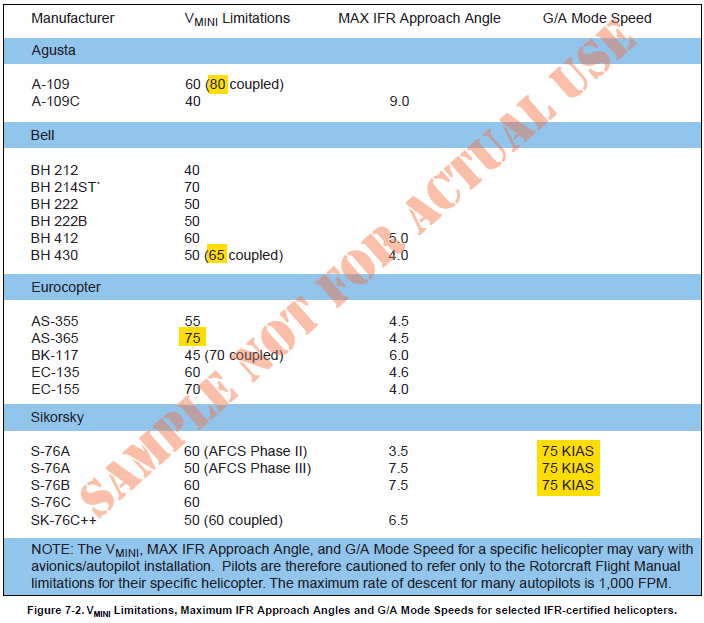
Final approach angles/descent gradient for public approach procedures can be as high as 7.5 degrees/795 feet per NM. At 70 KIAS (no wind) this equates to a descent rate of 925 FPM. With a 10-knot tailwind the descent rate increases to 1,056 FPM. “Copter” PinS approach procedures are restricted to helicopters with a maximum VMINI of 70 KIAS and an IFR approach angle that will enable them to meet the final approach angle/descent gradient. Pilots of helicopters with a VMINI of 70 KIAS may have inadequate control margins to fly an approach that is designed with the maximum allowable angle/descent gradient or minimum allowable deceleration distance from the MAP to the heliport. The “Copter” PinS final approach segment is limited to 70 KIAS since turn containment and the deceleration distance from the MAP to the heliport may not be adequate at faster speeds. For some helicopters, (highlighted yellow in Figure 7-2) engaging the autopilot may increase the VMINI to a speed greater than 70 KIAS, or in the “goaround” mode require a speed faster than 70 KIAS. It may be possible for these helicopters to be flown manually on the approach, or on the missed approach in a mode other than the G/A mode. Since slower IFR approach speeds enable the helicopter to fly steeper approaches and reduces the distance from the heliport that is required to decelerate the helicopter, you may want to operate your helicopter at speeds slower than its established VMINI. The provision to apply for a determination of equivalent safety for instrument flight below VMINI and the minimum helicopter requirements are specified in Advisory Circulars (AC) 27-1, Certification of Normal Category Rotorcraft and AC 29-2C, Certification of Transport Category Rotorcraft. Application guidance is available from the Rotorcraft Directorate Standards Staff, ASW-110, 2601 Meacham Blvd. Fort Worth, Texas 76137-4298, (817) 222-5111. Performance data may not be available in the
Helicopter Flight Manual for speeds other than the
best rate of climb speed. To meet missed approach
climb gradients pilots may use observed performance
for similar weight, altitude, temperature,
and speed conditions to determine
equivalent performance.
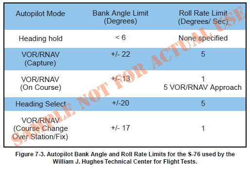
When missed approaches utilizing a
climbing turn are flown with an
autopilot, set the heading bug on the
missed approach heading, and then
at the MAP, engage the indicated
airspeed mode, followed immediately
by applying climb power and
selecting the heading mode. This is
important since the autopilot roll
rate and maximum bank angle in
the Heading Select mode are significantly
more robust than in the NAV
mode. Figure 7-3 represents the
bank angle and roll limits of the S-
76 used by the FAA for flight testing.
It has a roll rate in the Heading Select mode of 5
degrees per second with only 1 degree per second in
the NAV mode. The bank angle in the Heading Select
mode is 20 degrees with only 17 degrees in the NAV
Change Over mode. Furthermore, if the Airspeed
Hold mode is not selected on some autopilots when
commencing the missed approach, the helicopter
will accelerate in level flight until the best rate of
climb is attained, and only then will a climb begin.
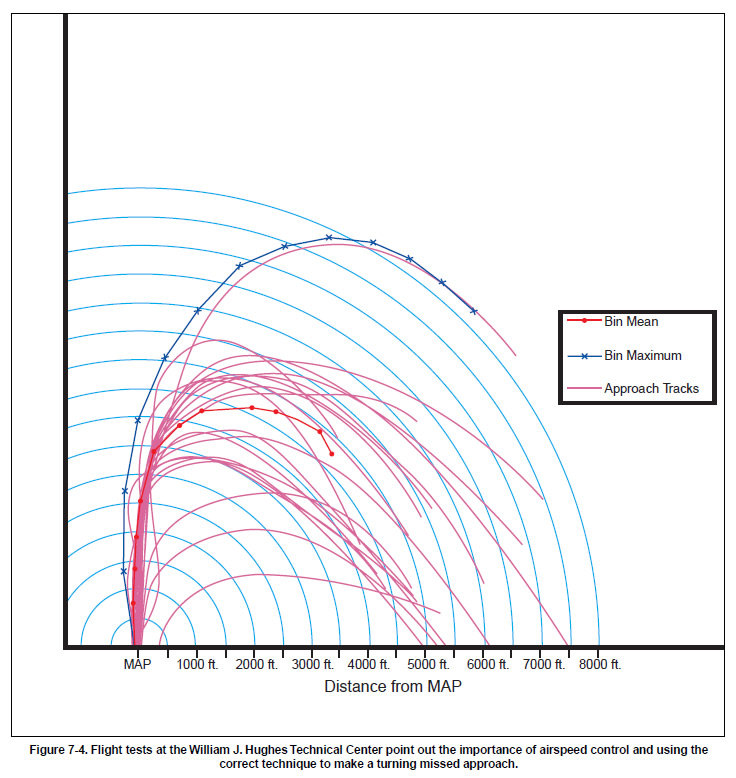
Wide area augmentation system (WAAS) localizer performance (LP) lateral-only PinS testing conducted in 2005 by the FAA at the William J. Hughes Technical Center in New Jersey for helicopter PinS also captured the flight tracks for turning missed approaches. [Figure 7-4] The large flight tracks that resulted during the turning missed approach were attributed in part to operating the autopilot in the NAV mode and exceeding the 70 KIAS limit.
|